
|
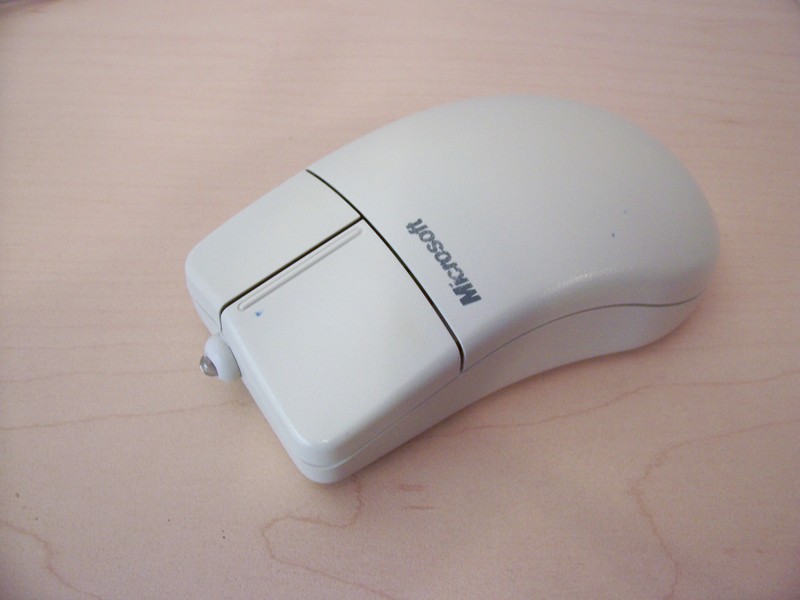
Most of us have a bunch of these old mice laying around collecting dust. If you didn’t make some cool art with your mice last week here is another idea to recycle it into a cool project. This article will show you how to turn an ordinary mouse into a flashlight, perfect for looking into computer cases that always seem to be in the darkest corner of the room. |
|
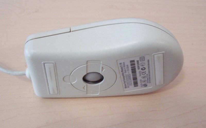
Look to see how to crack the mouse open. Most have some visible screws on the bottom. This one doesn’t… |
|
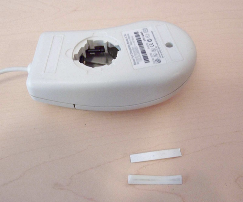
After removing the glider pads the single screw is revealed. Removing this screw is all it takes to open the case. |
|
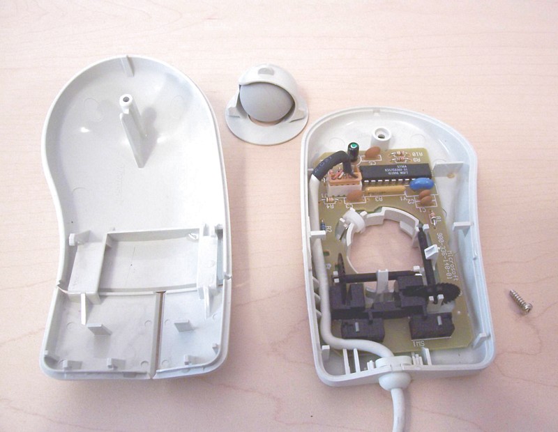
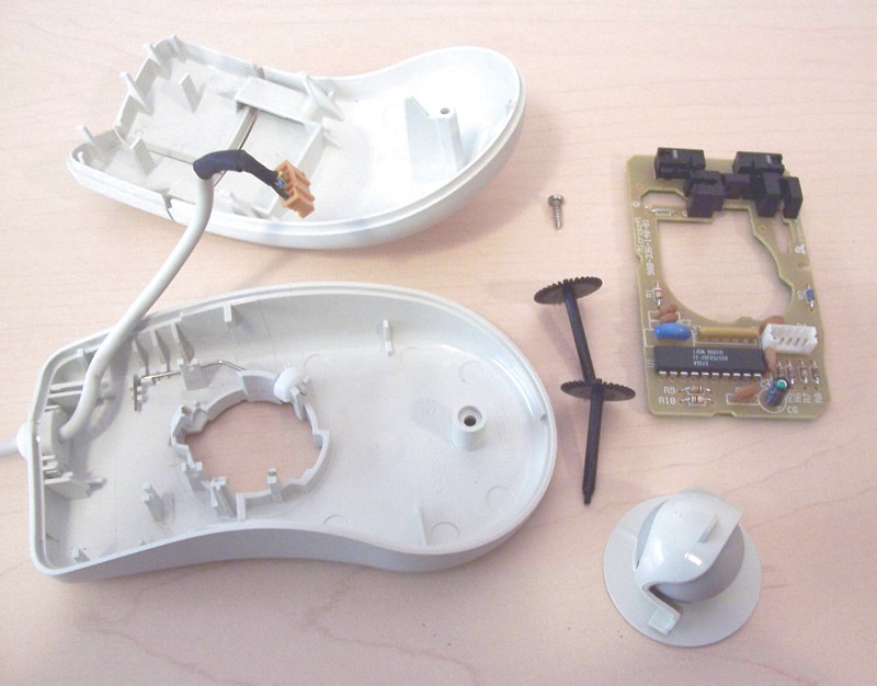
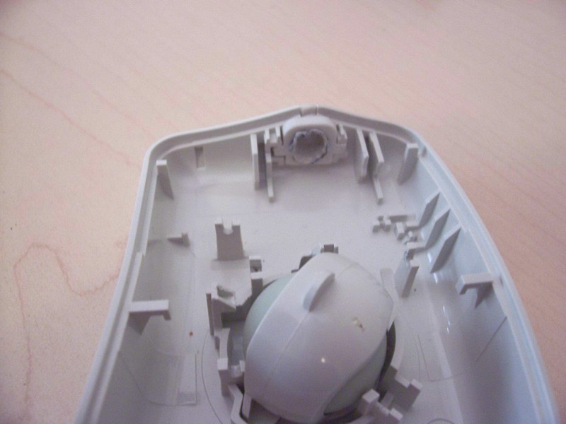
This is a typical mouse. Lots of room and a big roller ball in the middle. |
|
Start carefully removing the guts. Most of the components in this one were just slotted into place. |
|
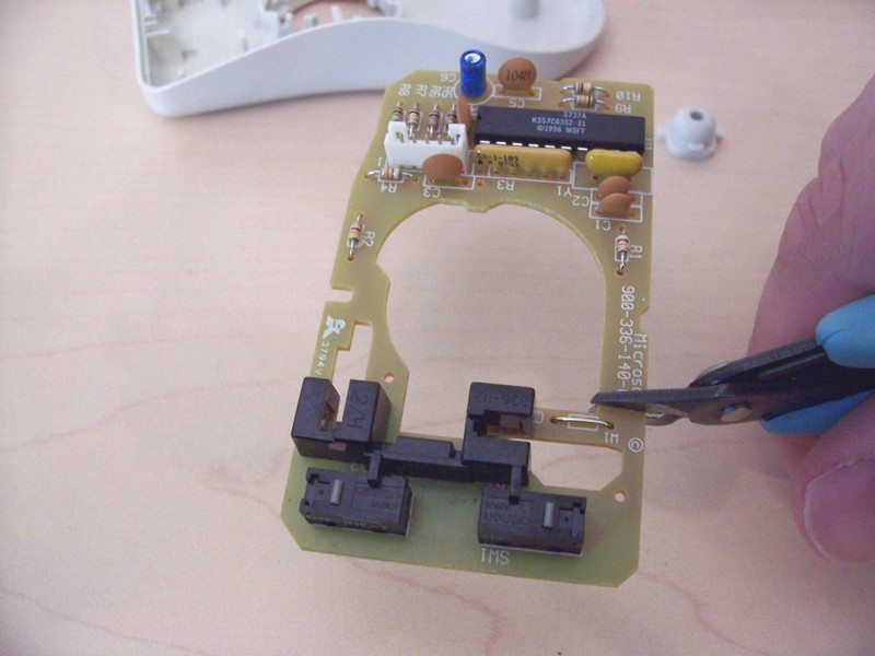
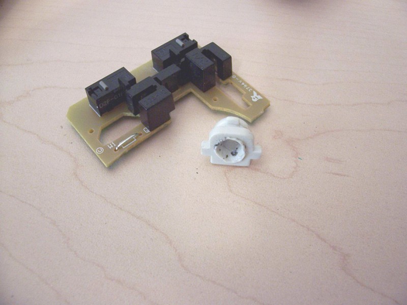
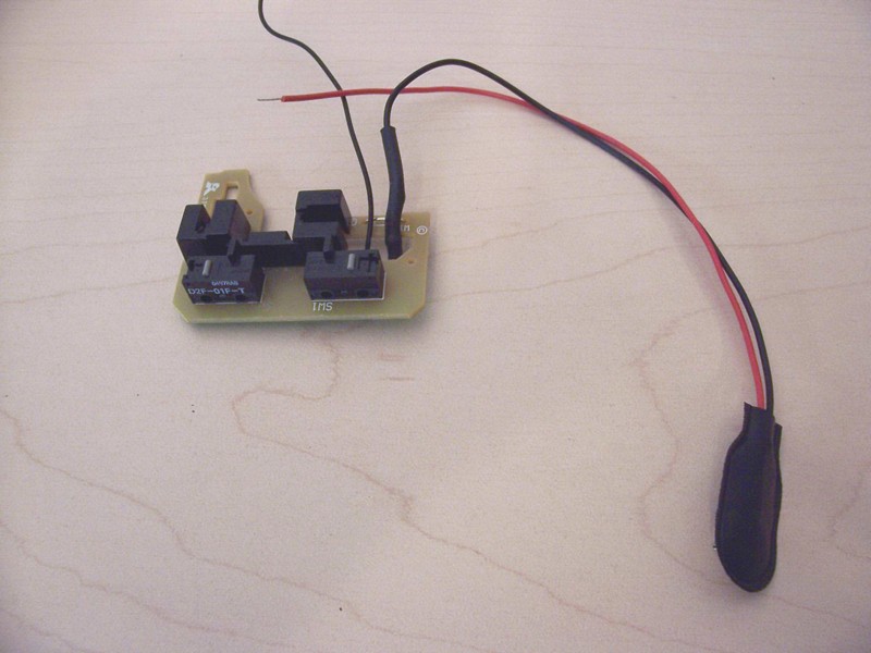
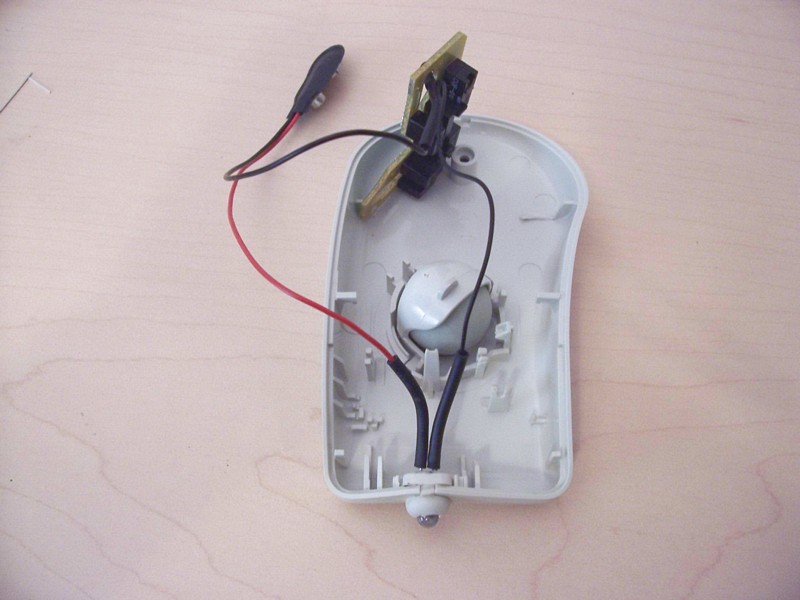
To make room for this mod the circuit board will be cut. This is also a convenient way to disconnect the switch that we will be using from the original circuit. |
|
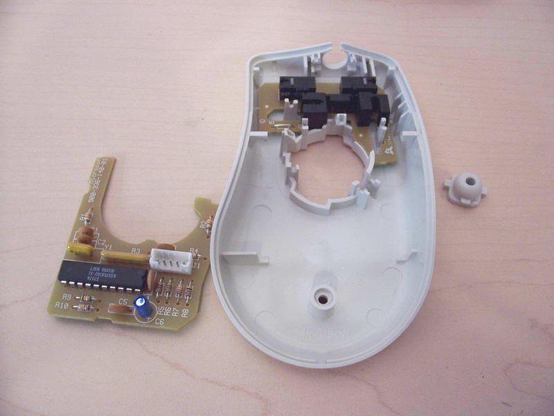
As you can see with the modified board installed there is now lots of room to play with. |
|
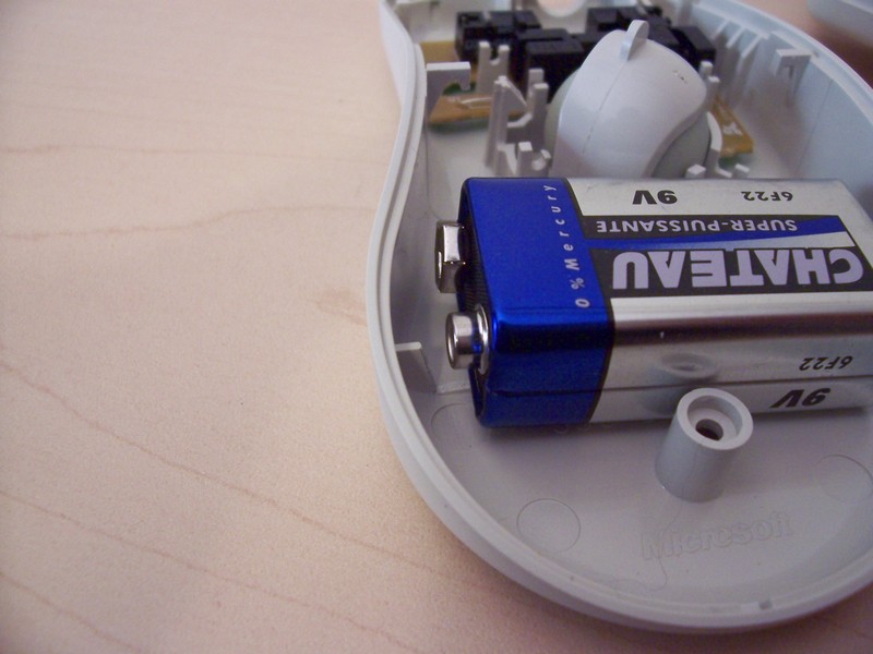
A plastic fin on the top cover had to be trimmed to allow the battery to be installed. A simple snip of the side cutters is all it took. |
|
There was also a small clearance issue with the side of the battery, we need this extra room since there will be a battery snap attached to the battery. Again the side cutters made easy work of the plastic fin. |
|
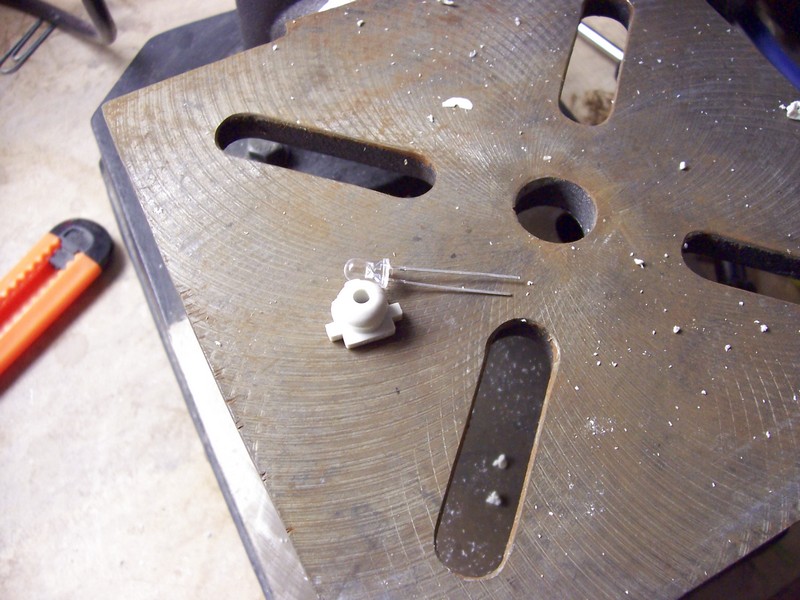
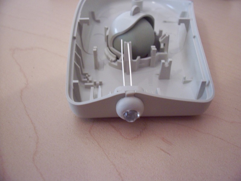
I decided to use the original wire grommet as the LED hole. The wire diameter is smaller than the 5mm white LED that will be installed. |
|
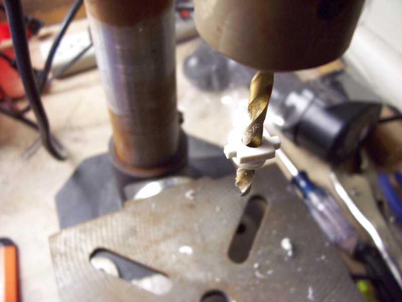
The drill press is overkill to enlarge the hole but it was handy. |
|
The base of most LEDs have a flange, to accommodate this I simply used the tip of a soldering iron to melt away a some of the back of the grommet. |
|
This mouse is designed quite well, the grommet slides right back into place with ease. |
|
The LED is now slid into the grommet. Use a bit of hot glue if it is a loose fit, in this case it is held in there quite well with no glue. |
|
Next we will solder some current limiting and one battery snap lead to the mouse switch. I am using the left click switch in this case. It is usually very easy to tell where to solder to since most mouse circuits use only N/O (normally open) switches which is what we need. If the switch has three connection you are usually safe to use the same ones that the original mouse circuit used. |
|
Next I used some heat shrink to cover the resistor and bare wires. |
|
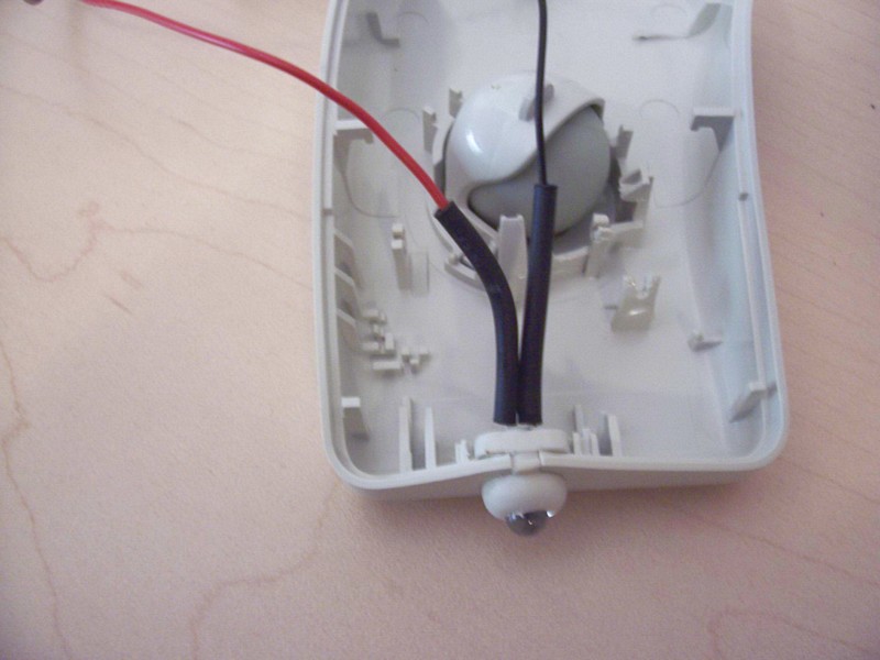
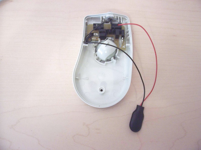
Some wires are now connected to the LED and heat shrink is used to cover the bare wires. Red from the battery snap and the wire from the switch are used. |
|
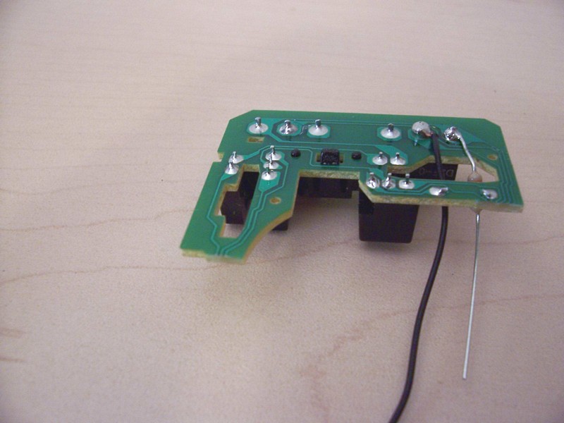
That is the entire circuit done. You can connect the battery now and give is a test. |
|
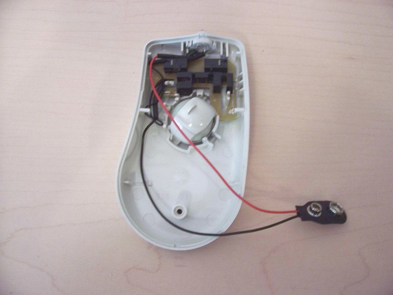
Another shot from the side. |
|
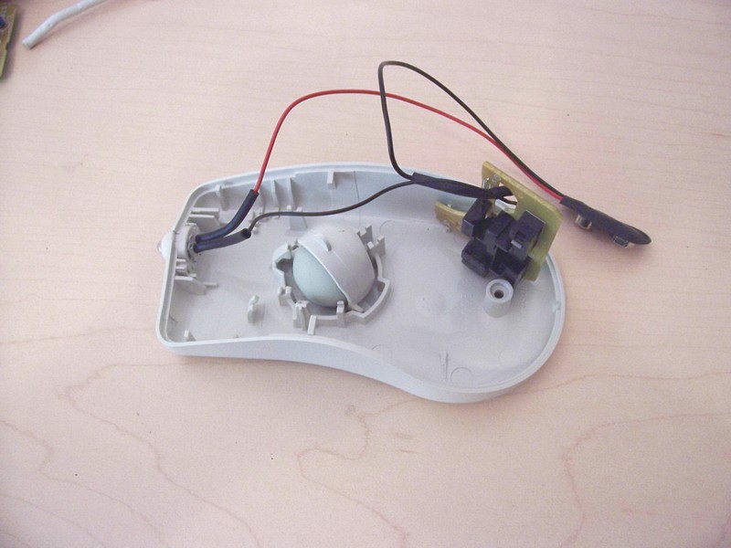
Slide the board back into place. Depending on the model of mouse you may need a bit of hot glue to hold it in place. For this one that was not required. |
|
It is possible to have both switches control the single light, all you need to do is jumper the two switches together. |
|
Since we are going to keep the roller ball in place make sure it will not rub on the wires when the unit is closed up. |
|
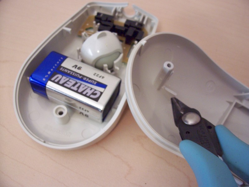
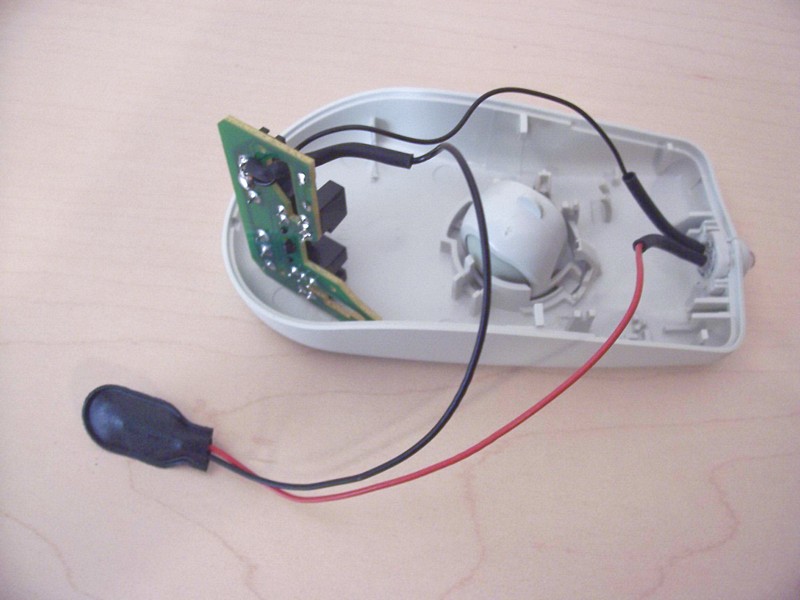
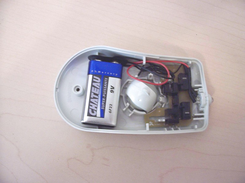
Connect the battery. In this case it fit quite well, if the case is a bit larger you might need some foam to keep it from bouncing around inside. |
|
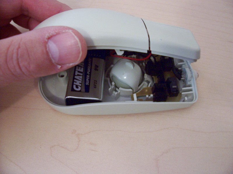
Close the lid making sure not to pinch any wires. |
|
That’s it, you now have a new flashlight. |
|
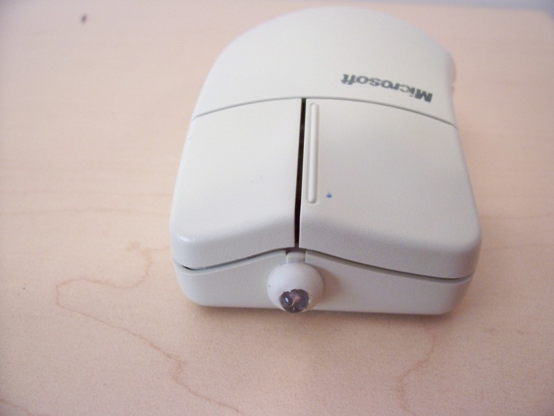
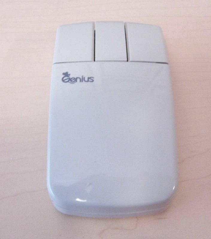
Looks a bit like one of the old optical cordless mice from the front. In fact when it was sitting on the desk I have grabbed it a few times and wondered why the mouse cursor wasn’t moving on the screen… |
|
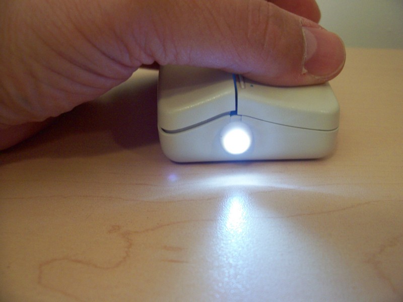
Give it a push and make sure it works. |
|
Now when you are working on your computer you can use a light that is cool and functional. |
|
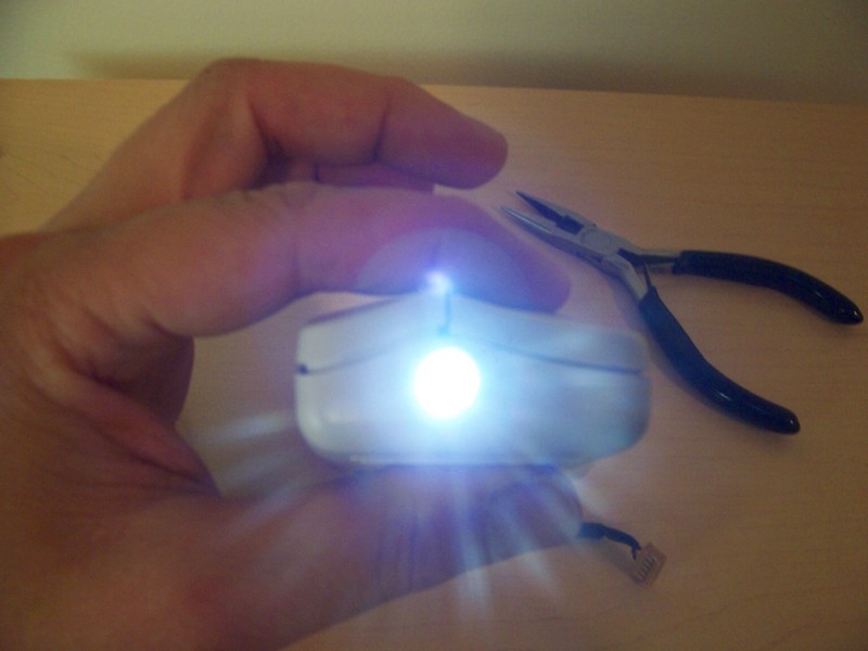
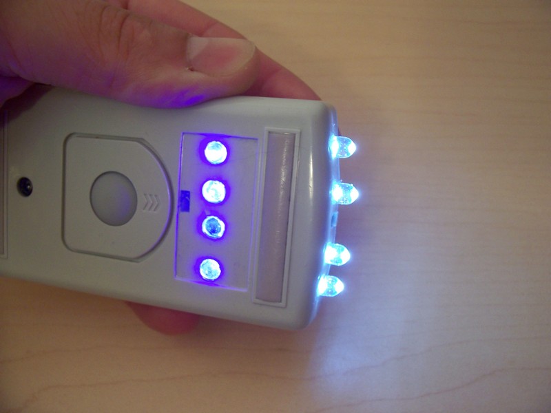
Here is a sneak peak of the next version of the LED mouse. |
|
This is a three button mouse that controls four white LEDs and four UV LEDs. The UV LEDs are on the bottom and are used to check for counterfit money, cheques etc. |
Permalink
i thought mouse can’t make anything. it is really cool. thanks for this information.
i will try to make one.
Permalink
Hey there, being a complete electronics novice I have a request for help. How do I identify which points to use on the bottom of the mouse switch? The mouse I am using is an old Mac one, with one large button on the top. I’ve opened it up and the swtich itself looks the same as the one you used. What gets soldered where? This will be my first ever electronics project so help is much appreciated.
Permalink
Any hints on selecting a resister for current limit? I made a flashlight and I found that simply sub. Led V from batt. V and cal. the res. value doesn’t work. I used a 3.6 V led on a 6 V batt. I ended up with a 30 ohm 10 watt. I think what happens is those little batt. Get dragged down pretty easy.
Permalink
Hi Luke,
The Black lead from the battery snap is connected to a resistor, the other end of the resistor is connected to one side of the switch. The other side of the switch is connected to the cathode of the LED (Side of the LED with short lead and flat spot on the LED base). The last connection is the red battery snap wire to the LEDs anode. There are many ways to arrange the components, this is only one. Basically as long as the polarity is correct on the LED and the there is a series resistor and normally open switch you will be good to go.
As far as the switch goes if you have a three terminal switch there is a very good chance that the mouse also used a normally open contact so simply look for which connection the original circuit was using and connect to the same points.
Permalink
Hi Ben,
Go here to calculate the resistor value you need.
http://alan-parekh.com/led_resistor_calculator.html
For 6 volt go with something around 150 ohms, 1/4 Watt size will be fine. Or for 9 Volt use something around a 330 ohm as noted in the article. (beside the first picture)
Permalink
Thanks loads, I’m making one this week!
Permalink
Dood, thats awesome, i made one using an old apple mouse, the old ones with only one button, its totally awesome and it works great!!!
Thanx for the idea!!!
~Pie
Permalink
Hi! This project is great but im wondering if i have to change anything when using an led of an other color.
Permalink
hey thanks for the ideai made one myself and it works really well. when will you have the new one ready plus do you know if u could combine a dimmer switch into it so when you roll the scroller up or down it gets brighter or dimer? thanks for the idea it rocks !
Permalink
Hi Max,
The value might change depending on the type of LED. What LED were you wanting to use?
Alan
Permalink
Hi Elliot,
You could but you would have to install a potentiometer since the scroll wheel is not a pot (it is just an optical sensor)
Permalink
Hey Mate,
cheers for the idea. I thought it was awesum so i found an old serial mouse lying around and made it myself.
Permalink
Really nice idea, pretty creative, I think. I do have a question, however. Would it be possible to have the left mouse button turn the LED on (without having to hold it down), and then the right mouse button turn the LED off? I don’t have too much experience with circuitry, so go easy on me if you can =). Thanks for the instructions, also! I’m gonna try to do this =).
Permalink
Chase B:
You could fairly easily adapt it to click-on, click-off; or left-on, right-off. One way to do that would be to incorporate a flip-flop IC. Another possibility is to use a relay. The relay is a fairly simple circuit, but requires that one of the switches is normally closed (push-to-break).
The basic idea of the relay circuit is to make the relay behave as a latch. To do this, the (N.O.) “on” switch is wired in series to the (N.C.) “off” switch and load. The relay coil is then wired in parallel to the load, and the (N.O.) relay contacts are wired in parallel to the “on” switch. It is also necessary to wire either a resistor or (preferrably) a reverse-biased (that means, opposite polarity) diode in parallel to the relay coil, to protect the LED and switches from the coil’s back-EMF.
The circuit works as follows: When the (normally open) “on” switch is pressed, the relay coil (and load) is energized. This causes the relay contacts to close, bypassing the “on” switch. The circuit then stays in the “on” state until the (normally closed) “off” switch is pressed. This then breaks the circuit, causing the relay coil to de-energize (through the protection diode or resistor), and the relay contacts to open.
Permalink
Below is an attempt at a schematic. Try viewing it with a fixed-width font.
+V _[]_”on” “off” ____ resistor
o-*- -*—-_[]_—*—*—–|____|—,
| | | | |
|__/ __| 3 _|_ _|_
N.O. relay 3 /_\ diode \ / \ LED
contact coil 3 | 1N4004 _V_ \
3 | |
GND | | |
o——————–*—*————–‘
Permalink
This document is mentioned at the Repair4Mouse Microsoft mouse repairing and cleaning guides section.
Permalink
well, note that there might be a slight problem…
when you connect both wires to the switch, with my mouse it completed the circle. because it didnt need the switch but the rest of the circle of the original mouse. Try to cut those!
——Battery——-
|………………|
——-switch——-
|………………|
Permalink
Im gonna do this with the old mouse to this PC im on now the wires from the cord that run to the mouse’s PC board the solder points were broken so it wasnt working so im gonna rig the switches so when you click any of the buttons it has 2 buttons and a clickable scroll wheel and when you click either one of them the LEd will light, im gonna use a White LED like seen in this mod and a 4.5 volt AAA battery pack if i got one lying around and I might record a video of it but i dunno about that i dont really have the recording facilities to do this (no tripod for the camera/ not big enough of a card)
Permalink
I did this and ive had it a little i just need to get that resistor but for now im using dead batteries instead of new ones but the mouse flashlight is together and ive made a video of it its saving right now and ill get it up on youtube and ill be back with the links
Permalink
OK I have the video up on youtube you can check it out here http://www.youtube.com/watch?v=vVt5uEwZ41A
Permalink