
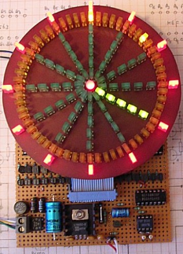
Ronald Dekker put together an LED clock using a PIC 16F84 microcontroller. Some people would wonder why a $5.00 clock from the store couldn’t be used. It could be, but where would the fun be in that?
“The 16F84 processor used here is a little bit out dated and no longer in production. I used it because of the simple fact that I had it lying around. The more modern 16F628 is pin compatible and will perform equally well. The 16F84 has too few I/Os to address all the anode and cathode drivers directly (Fig. 3). A 74HC563 8 bits latch was used to extend the number of outputs by another 8 bits at the expense of a latch enable signal taken from port A. The eight outputs from the latch, together with the lowest 4 bits of port B from the PIC drive address the cathode drivers. Since only one of the anode rows is switched on at any given moment, a HEF4028 1-of-10 decoder could be used to activate one of the six rows using only 3 bits (A0…A2). These bits are connected to the higher 4 bits of port B. To prevent unwanted illumination of LEDs during the multiplexing of data to the 74HC563, I/O bit A3 from port A is used to completely disable all the anode drivers. ”

Permalink
silicon cementery
Permalink
cool
Permalink
Nice!
It’s possible get the circuit squematic, list of components and of course the program’s PIC?
i wanna do this project! it’s very nice stuff!
Permalink
Click on the link in the article, looks like code and circuit are provided. 🙂
Permalink
nice! can this be modified on 60hz ac mains? thanks!
Permalink
hi
i need colok circuit,plz help me
tank you
Permalink
hi. can you explain how to make this clock?
Permalink
i need this clock circuit. what program it has? please answer me?