
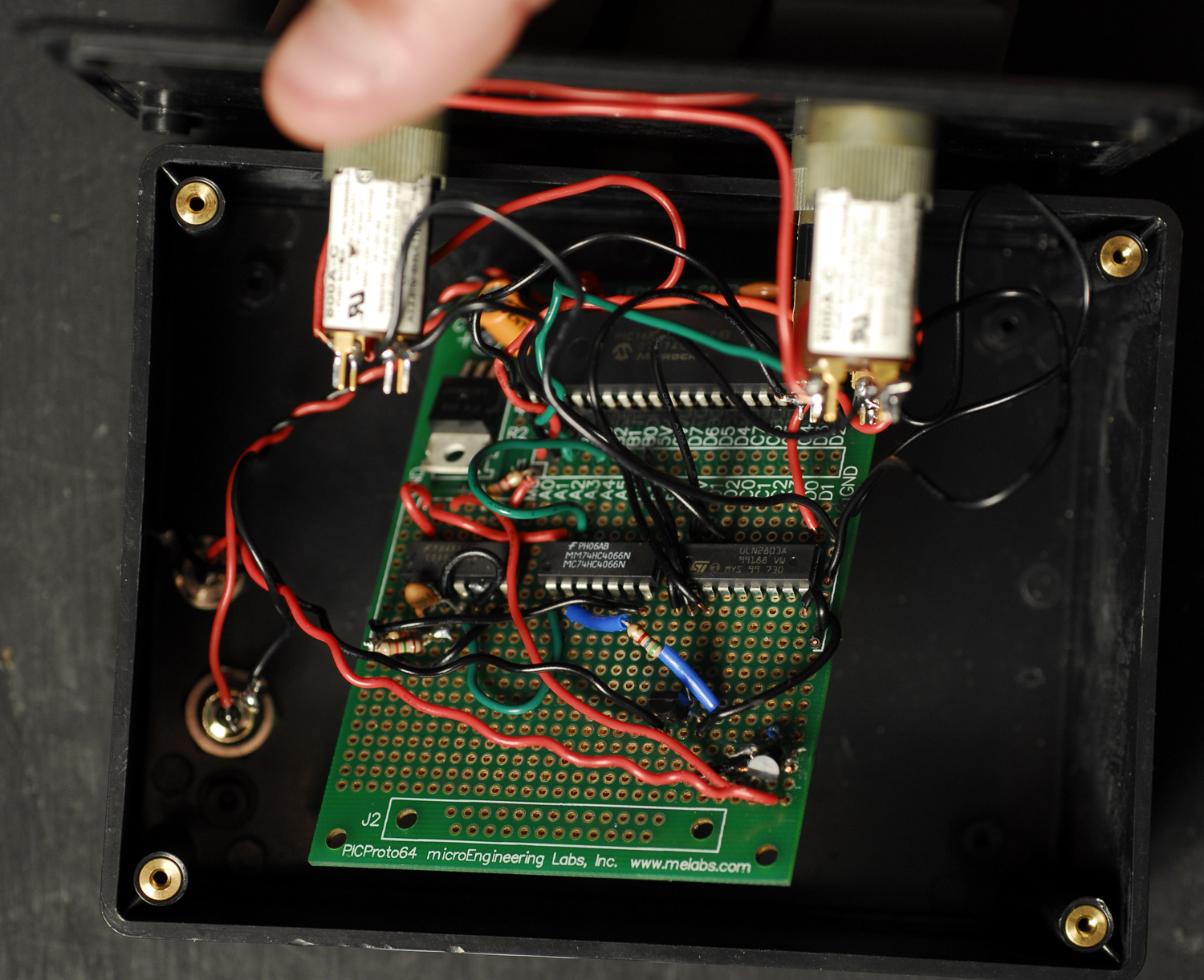
ElectronicsNerd shows us how to reverse engineer an IR remote control signal. By understanding what type of signal is being transmitted out of the remote control allows a microcontroller to simulate the code to control the Hampton Bay Air Conditioner.
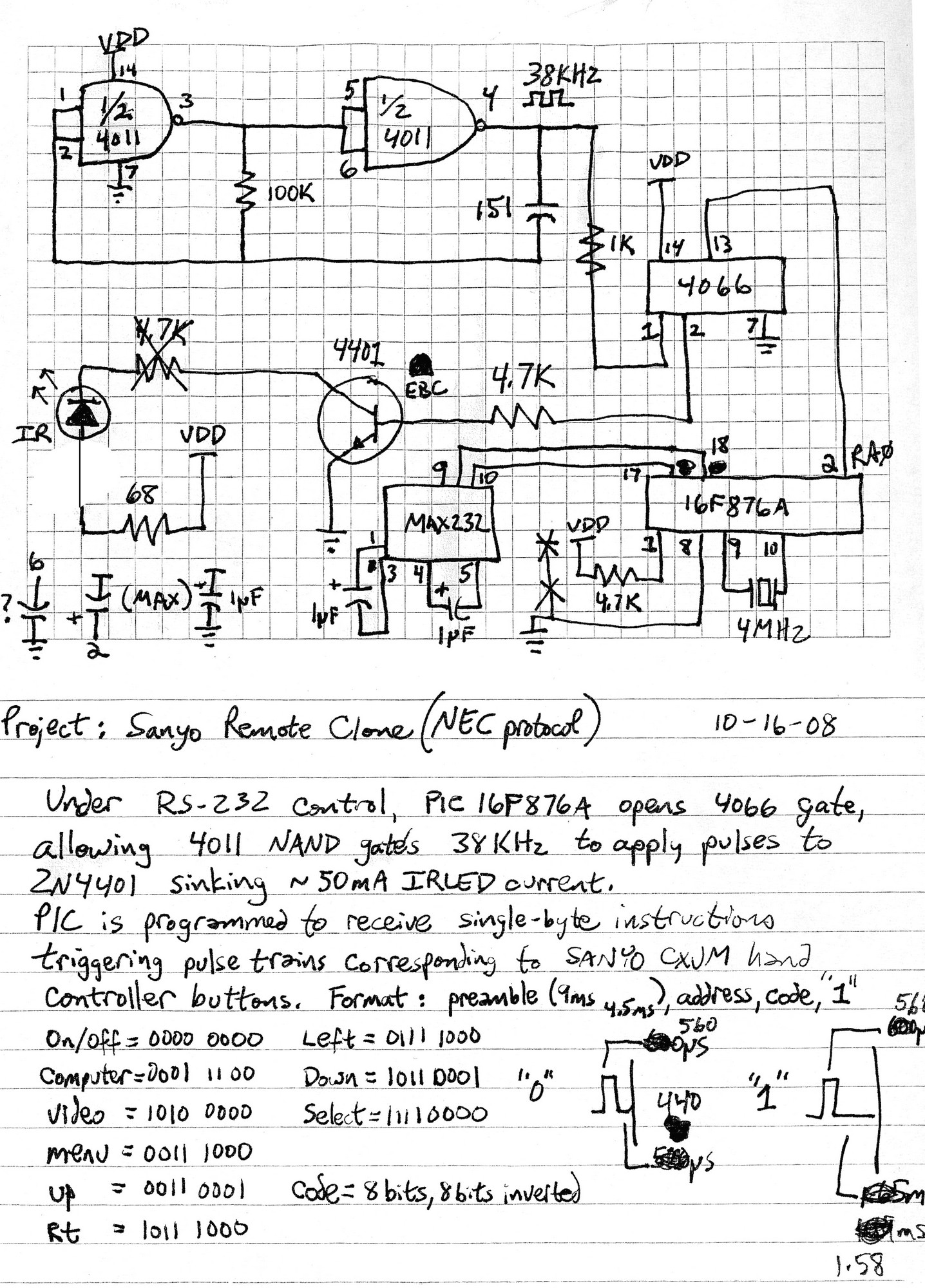
"In the NEC protocol, the initial start pulse prepares the receiver IC for a data transmission at a particular rate, adjusting its AGC circuitry for the signal level excursions of what is to follow. After the standard 9ms equalization pulse, there’s a 4.5ms pause, and the receiver then accepts data at a predefined baud rate. If one weird spike were to occur at a particular moment during the transmission, the air conditioner might turn off instead of lower the setpoint temperature of the unit, without a means for detecting glitches in a transmission. Simple error checking like this provides for disallowing invalid input, while providing near-failsafe transmission of valid control data."
Permalink
Maybe I’m just a CD4000 series hater from way back, but 4MHz / 26 / 4 ~= 38kHz (±1%) – two packages – a continuously running oscillator…
Permalink
I had the same thought as you about the oscillator, not to mention he’d get better precision from the quartz. Even if he didn’t want a software oscillator the 4066 is completely unnecessary, he could have just wired RA0 to pin 1 of the 4011.
Permalink
You two are right. I guess I’d have to square the divided crystal oscillator’s output? Thanks for the comments; I’ve been working at this stuff alone and it’s great to hear feedback.
Permalink
Nice to see our comments can be of some use sometimes :). What Jonathan and I meant was to get rid of the CD40xx chips and generate everything purely in software. The 38kHz are well within the capabilities of the PIC, but you may need to use a bit of inline assembly if PICBASIC is too slow or gives too little control over timings.
Another thing you want to do is pulse as much current as possible to the diode, to maximize the range. Usually diodes have a 20mA continuous rating, but 100mA pulse rating. It means that if you keep the duty cycle low, you’ll be able to use higher currents. It will also help save power if you’re running on batteries.
Here’s an example of some code you could use to generate the 38kHz bursts with 20% duty cycle, assuming a 4MHz clock (not tested). :
movlw .22 ; Number of 38kHz signal periods to generate.
movwf tmp_1
ir_loop
bsf PORTA, RA0 ; IR LED turns on here
nop ; Stay on for 5us
nop
nop
nop
bcf PORTA, RA0 ; IR off
movlw .5 ; Generate the remaining 17us delay
movwf tmp_2
decfsz tmp_2, f
goto $-1
nop
decfsz tmp_1, f
goto ir_loop