
Do you know someone who wants to learn a bit about electronics? Wiring up some components is the first step in starting the journey. Or maybe you just want to try out some of these cool Flashing RGB LEDs! With a total project cost of between $2.00 and $3.00 the time is right to try some of these things out. They can add some fun to the holidays that are just around the corner, these RGB LEDs will be on sale for the next while so that you can get some to spruce up the holiday season. 🙂
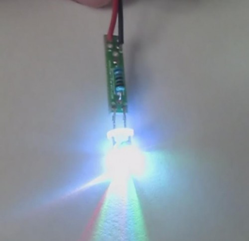
These LEDs are magic, inside the ordinary looking LED dome there is actually 3 LEDs along with a tiny controller that sequences the lights in some cool patterns. Stay tuned for a peek inside one of these LEDs! It first cycles the individual colors quite rapidly, and that is followed by some slow color fades where individual and multi-color slow fades are performed. All you need is a single current limiting resistor and you are in business!
Placement Ideas:
- Under the Christmas tree for a subtle effect amongst normal lights.
- Behind your computer monitor, this would force you to stay awake and get more work done. 🙂
- Light up your house door bell, no more plain white.
- Change the power on light in your computer or other equipment.
- Use it to light the inside of your computer case.
- Subtle above cabinet lighting, at night the effect would be cool.
- In a Christmas ornament.
- Lots of interior and exterior vehicle applications!
There are two projects listed below, one uses crimp connectors which means there is no soldering needed. The other uses out LED Mounting Board to solder all the components and leads to.
Solder Together Flashing RGB LED Project Video
Crimp Together Flashing RGB LED Project Video
Solder Together Flashing LED Project Assembly Steps
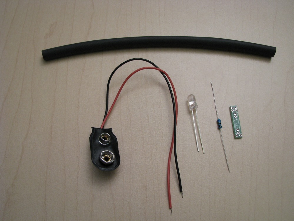 |
The parts needed are: 1 X 9 Volt Battery Snap Tools Needed: Soldering Iron & Solder |
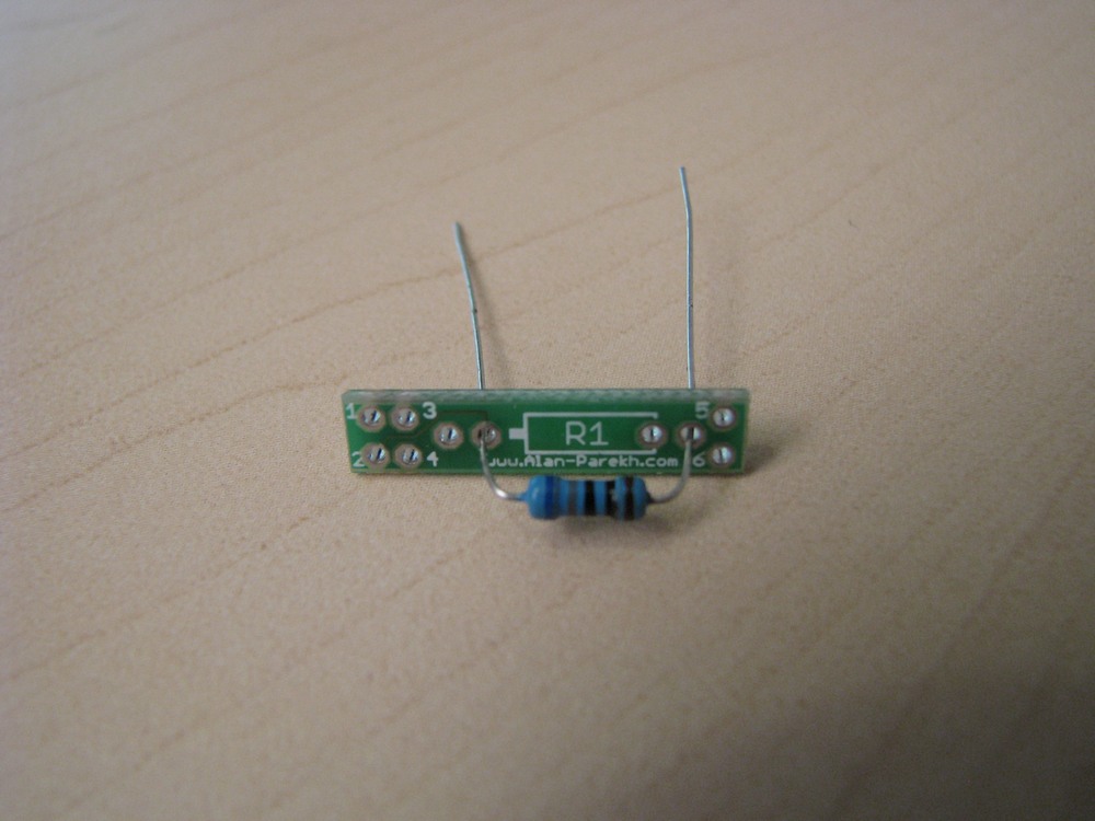 |
Mount resistor in location R1 |
 |
Spread the resistor leads to allow it to stay in place when soldering. |
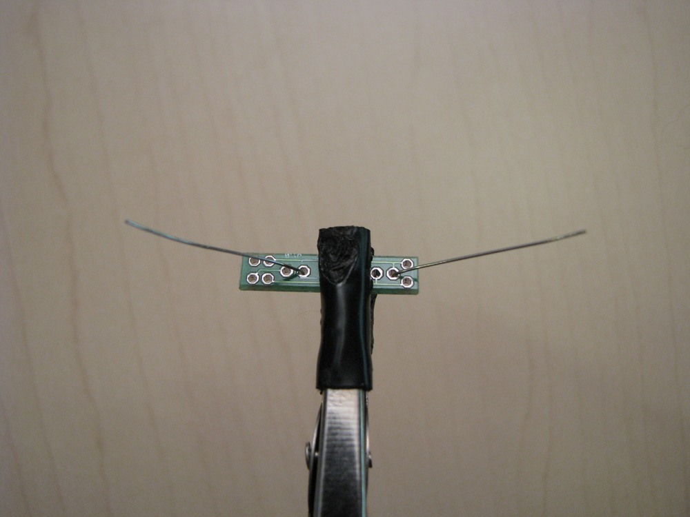 |
Solder the rear of the resistor leads. |
 |
Trim the resistor leads using a pair of side cutters. |
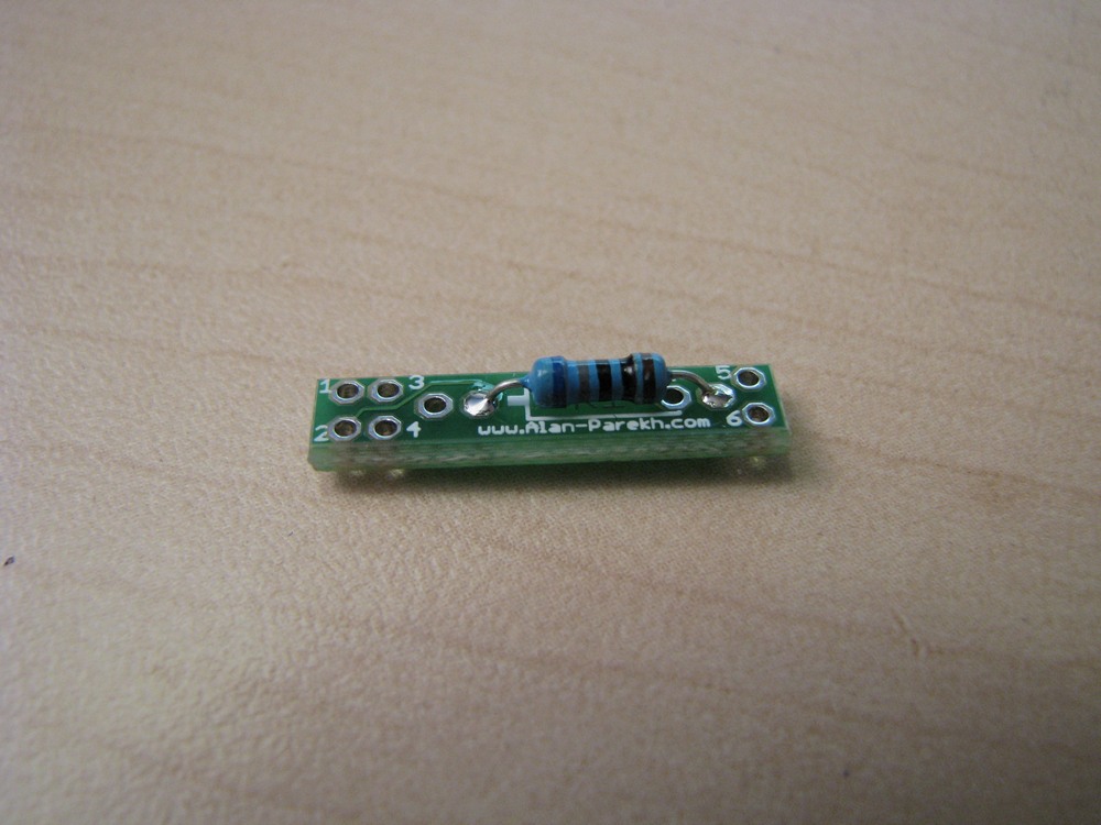 |
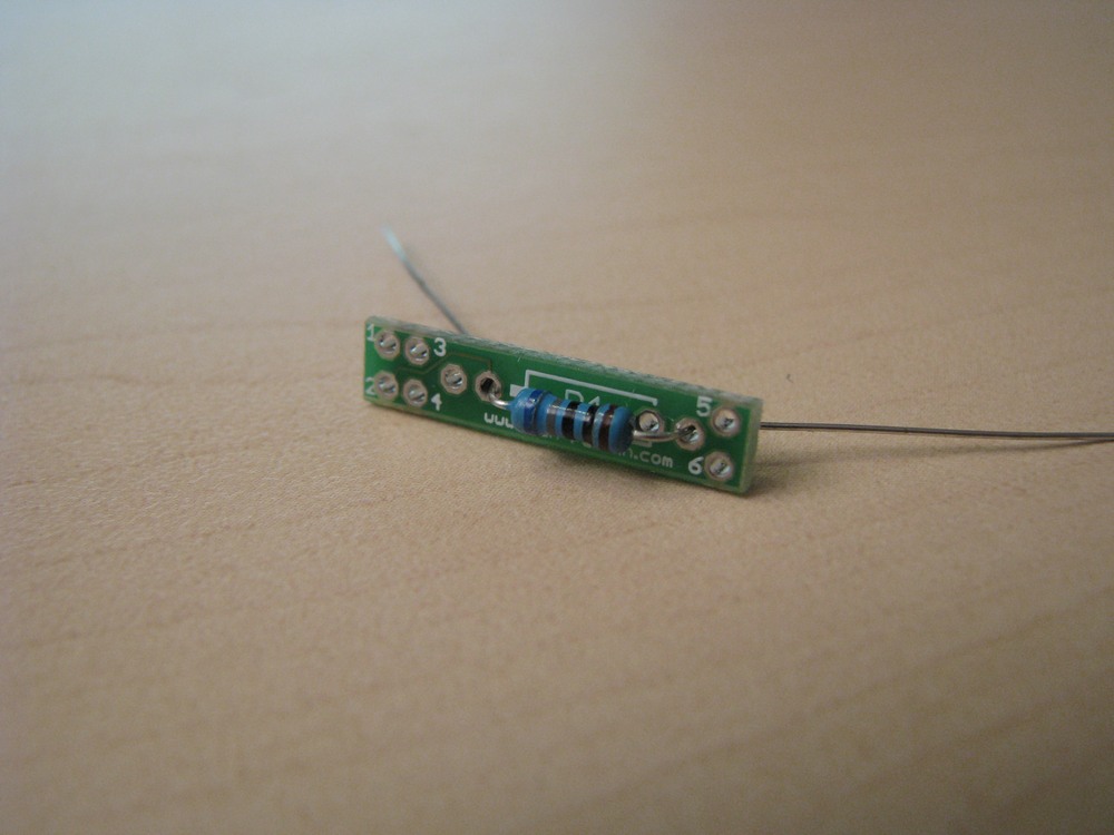
Resistor should be close to the board as shown. |
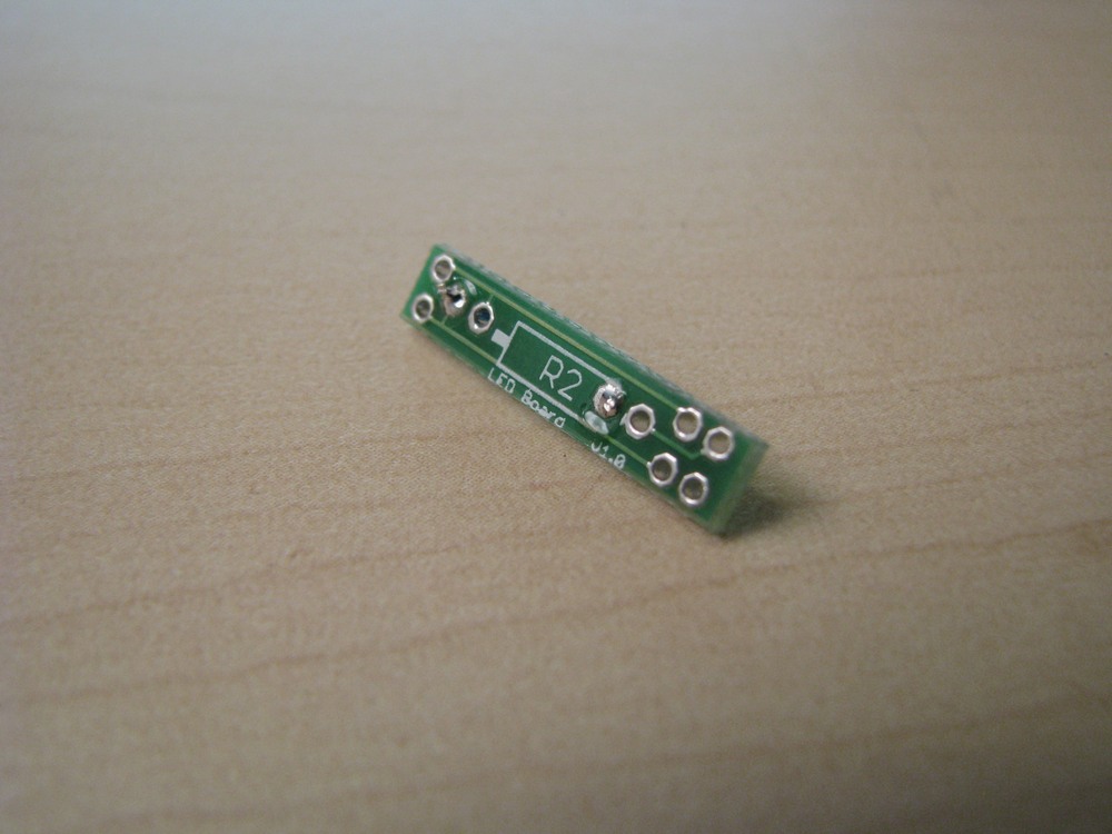 |
Back of board should look like this. |
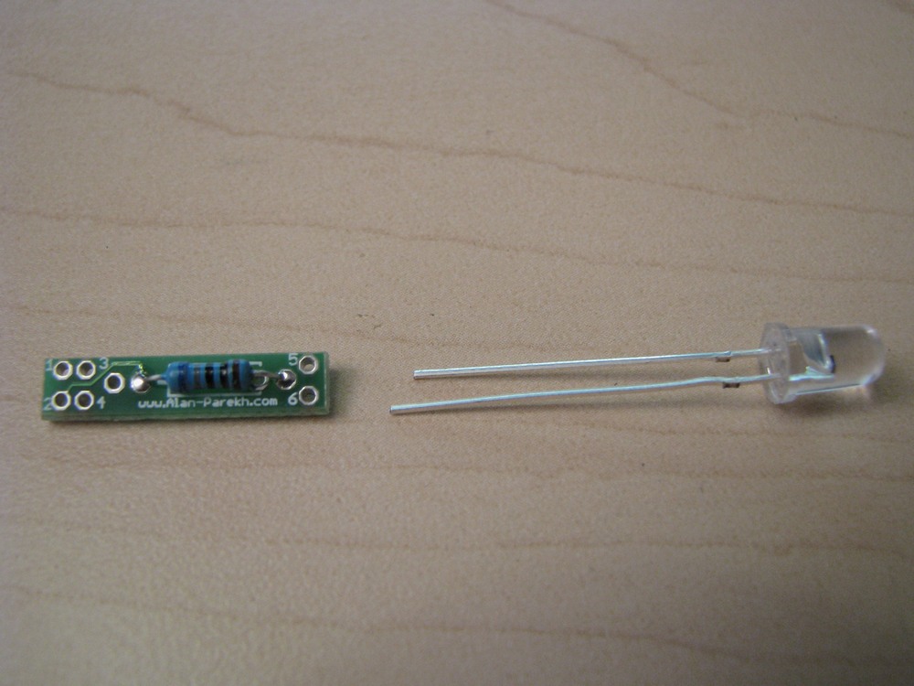 |
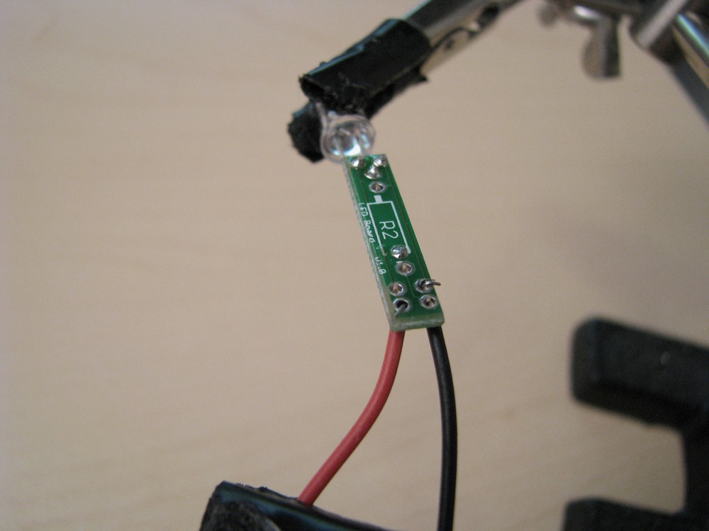
The LED is polarity sensitive. The short lead goes into the #5 hole, the long lead goes into the #6 hole. |
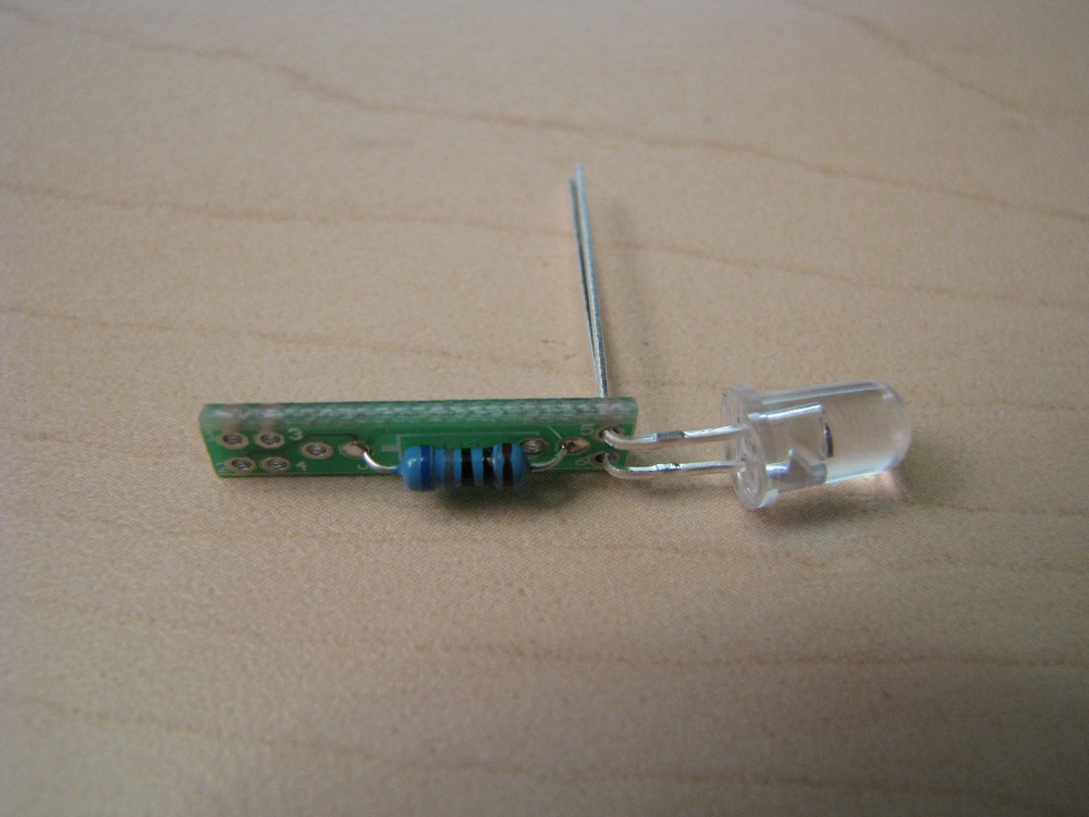 |
Bend the LED leads as shown. |
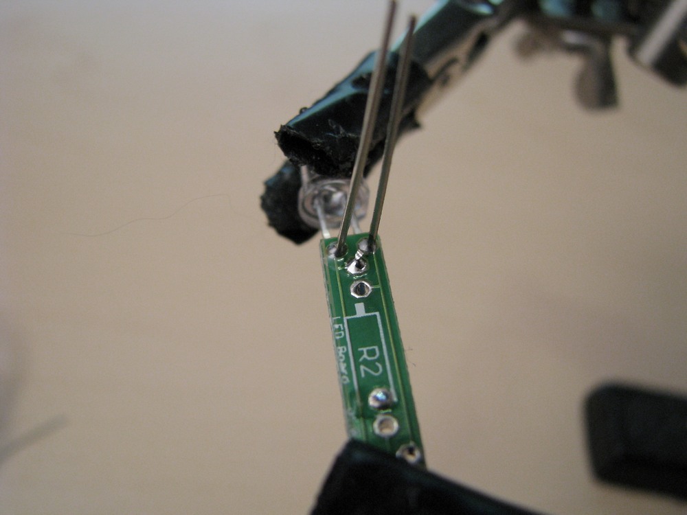 |
Solder the LED in place. Be careful with the application of heat. Too much heat will destroy the LED! |
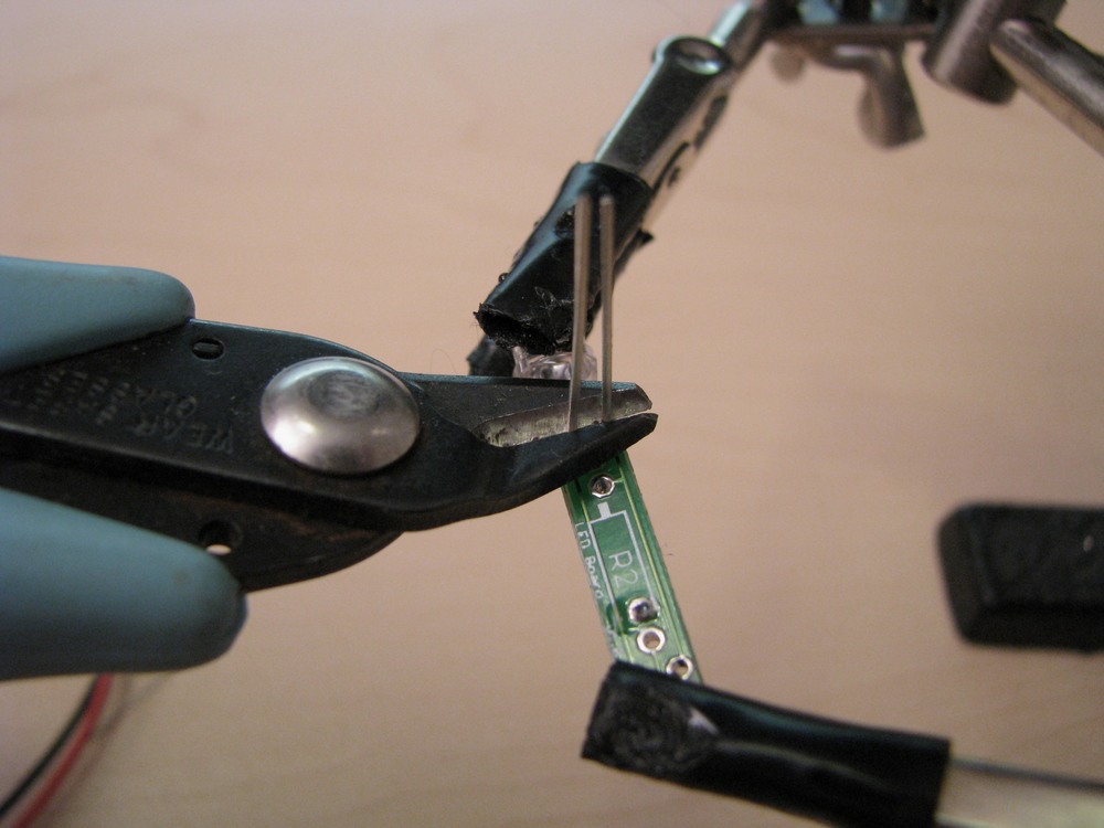 |
After soldering, clip the leads off. |
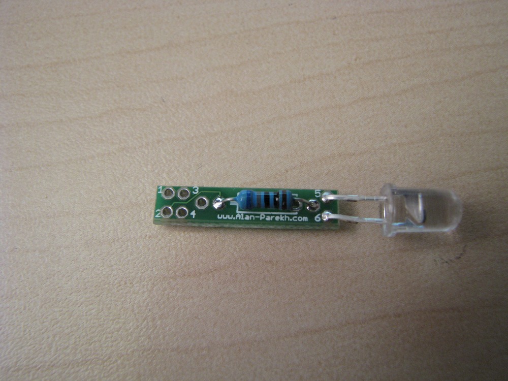 |
Your project should now look like this. |
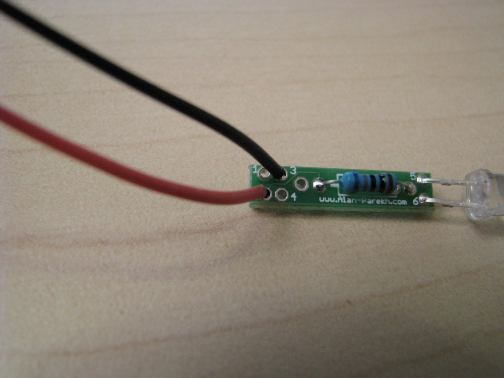 |
The black lead of the battery snap goes to the #3 hole, the red lead goes to the #2 hole. |
 |
Solder the wires in place. |
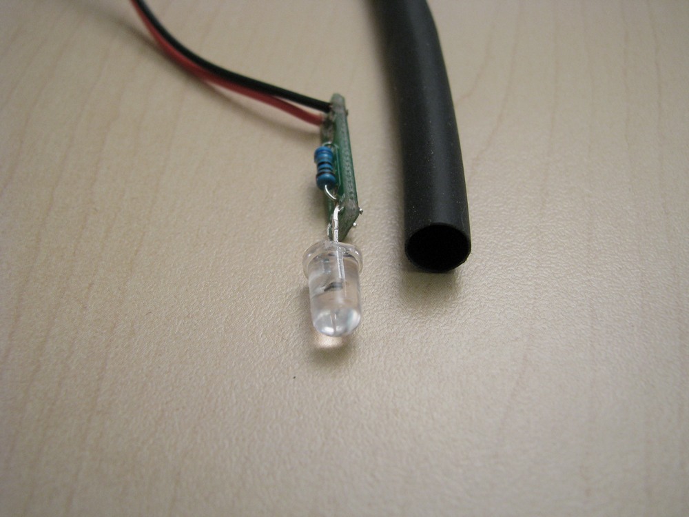 |
Heat shrink is optional. Either way you should test the operation of the device now. |
 |
Cut a section of heat shrink as shown and slide it in place. |
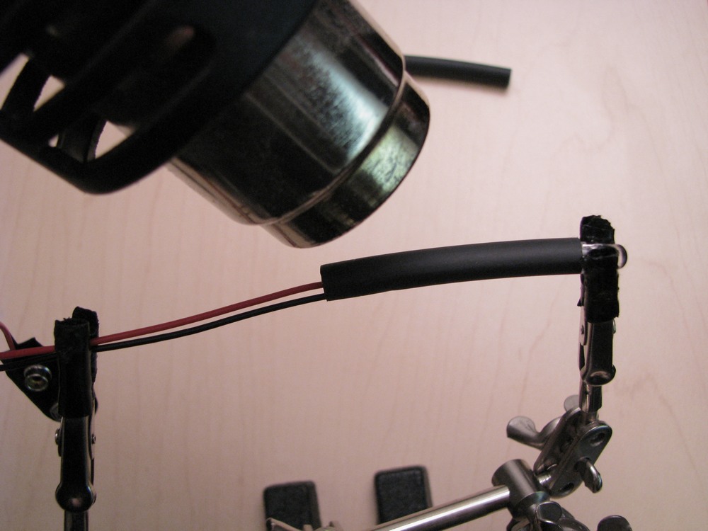 |
Heat the heat shrink very carefully. Do not heat up the LED, it will get damages easily during this step if you are not careful. |
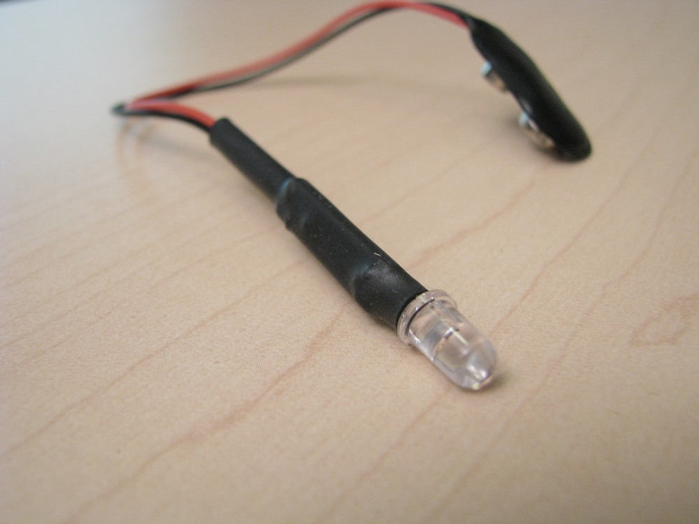 |
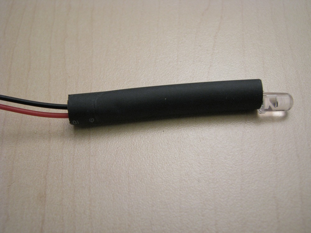
This is what the heat shrink should look like when completed. |
 |
All done. Plug it in and have fun! |
Crimp Together Flashing LED Project Assembly Steps
 |
The parts needed are: 1 X 9 Volt Battery Snap Tools Needed: Pliers to crimp connectors. |
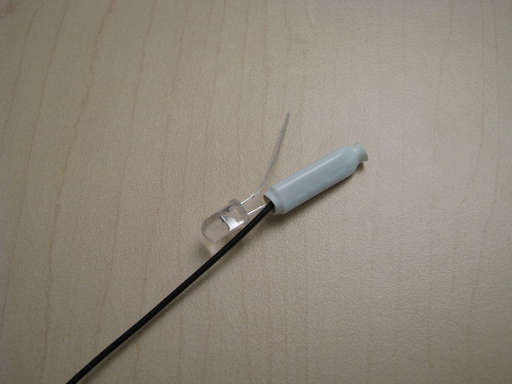 |
The black lead of the battery snap needs to be connected to the short lead of the RGB LED. Push them into the connector and use the pliers to squeeze crimp the connector. |
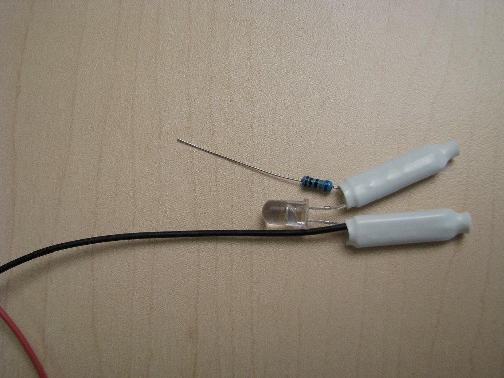 |
The long lead of the RGB LED needs to be connected to one side of the resistor. Push them into the connector and use the pliers to squeeze crimp the connector. |
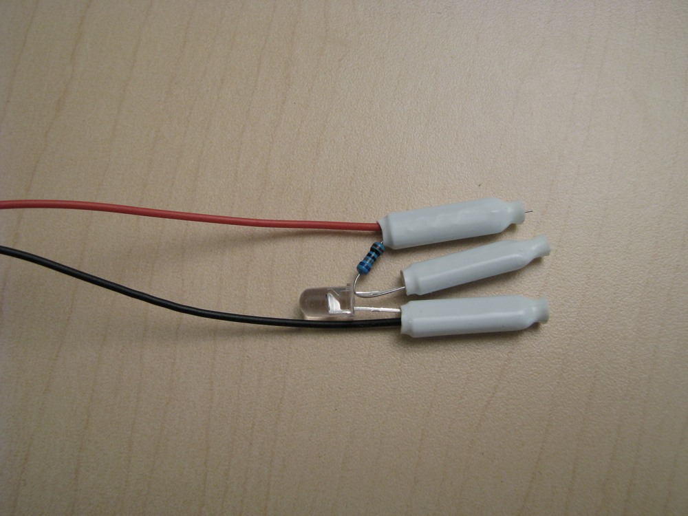 |
The other end of the resistor needs to be connected to the red lead of the battery snap. Push them into the connector and use the pliers to squeeze crimp the connector. |
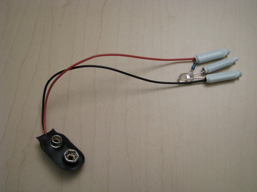 |
All done. Plug in a battery and give it a try. |
Permalink
It’s a bit basic, I’m not sure how much one can learn about electronics from this project…
I was hoping it was going to take 3 LEDs of different colours and do blending/flashing on the board (without an arduino or such), then you’d really be learning, perhaps even taking a non-flashing RGB LED and making it flash would be better.
That being said, I might make some of these with button batteries for ‘LED Throwries’ (http://graffitiresearchlab.com/?page_id=6)
Permalink
“This is a simple LED project, do you know someone who wants to learn a bit about electronic?”
Or grammar.
Permalink
Thanks Pete. 🙂
Permalink
Hi Carl,
Throwies would be a great use. I also saw some balloon throwies somewhere. Flashing balloons would also be a neat use!
Yes it is basic, something that anyone can do to get their feet wet.
Permalink
Sheesh, kids have it too easy these days, RGB transition effects needed 3 LEDs and a whole board of discrete components back in the days ! 😉 (just kidding)
Is this the beginning of a new series of electronics tutorials ? If so, good. The PCB might be a little bit unnecessary, however!
Permalink
This type of Videos we need more off !!
I like this !
Permalink
Soldering an LED to a resistor cant really be called a “project”.
Great video tho.
But, i would never cut the leads off after soldering – should be done before. Altho it doesnt mean much in the project, later on, it can be vital.
Permalink
Hi Vic,
You forgot to mention that you had to walk up hill in both directions to get to the electronics lab. 🙂
Permalink
Hey JDM,
I admit the term project is used very loosely for this one… Just something simple that kids (or anyone who hasn’t built something electronic) can tackle.
What is your reasoning behind pre-cutting the leads? I have never heard of that before.
Permalink
Hi Alan,
From what ive always heard, cutting the leads after soldering, gives a small shock into the solder – which might produce small cracks. If you then happend to have the electronics somwhere where the temperature rises and falls, you might end up with a solder that cant take the stress.
Permalink