Chris Savage from Savage Circuits goes over the basics of Rotary Encoder and Shift Registers in the second of his new video series called Savage Circuits TV. You can see all three videos here. If you are wondering why there is lots of Parallax gear used in the videos, that is because Chris works for Parallax. 🙂
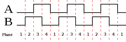
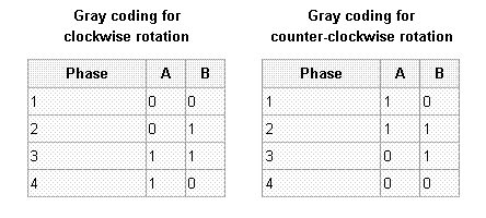
To read more about Rotary Encoders have a look at the Wikipedia page that also have a good example of Gray Code.
To read more about Shift Registers have a look at the All About Circuits page.
“An incremental rotary encoder, also known as a quadrature encoder or a relative rotary encoder, has two outputs called quadrature outputs. They can be either mechanical or optical. In the optical type there are two gray coded tracks, while the mechanical type has two contacts that are actuated by cams on the rotating shaft. The mechanical type requires debouncing and is typically used as digital potentiometers on equipment including consumer devices. Most modern home and car stereos use mechanical rotary encoders for volume. Due to the fact the mechanical switches require debouncing, the mechanical type are limited in the rotational speeds they can handle. The incremental rotary encoder is the most widely used of all rotary encoders due to its low cost: only two sensors are required.”


Permalink
Hi svofski,
Thanks for the video. I didn’t realize that controlling the head stepper in a floppy drive was that simple!