
|
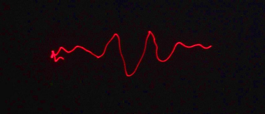
You might remember the Hard Drive Laser Oscilloscope from a few weeks ago. I have had many inquiries about how to build one. This page should give you enough details so that you can make your own. |
|
Basic Overview A hard drive voice coil circuit is hacked to allow it to be directly connected to a stereo output. This allows audio to move the hard drive read write head. Mirrors are positioned on the center of the platter and hinged on the side to allow a way for the laser to be moved in two axis. The read write head is connected to the hinged mirror so that they move together. And finally a laser is mounted to the hard drive pointing at the hinged mirror. Crank up the tunes and have fun! |
|
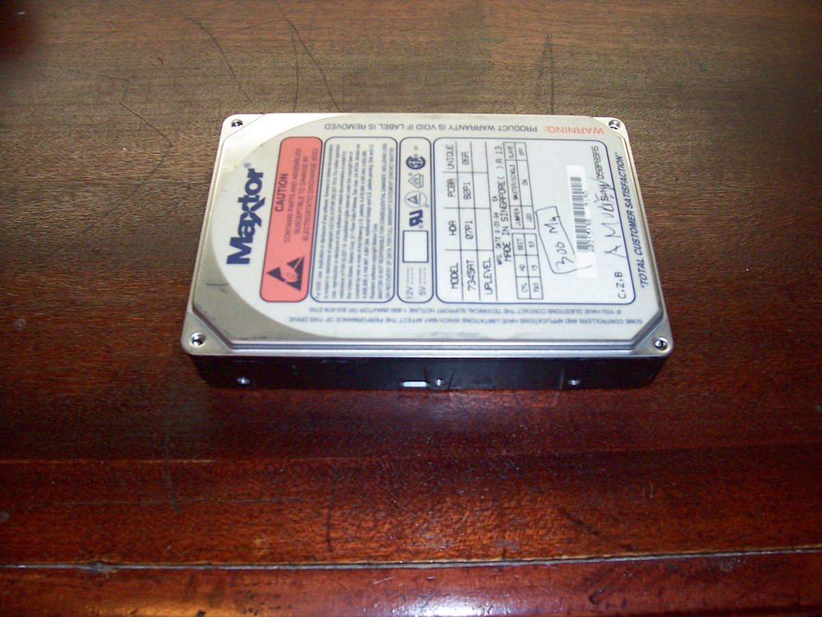
Find an old hard drive, I used an old Maxtor 300MB drive. Very old drives will not work for this project since the drive needs to have a voice coil actuated read write arm. Most drives around the 30MB size use stepper motors to move the read write arm. |
|
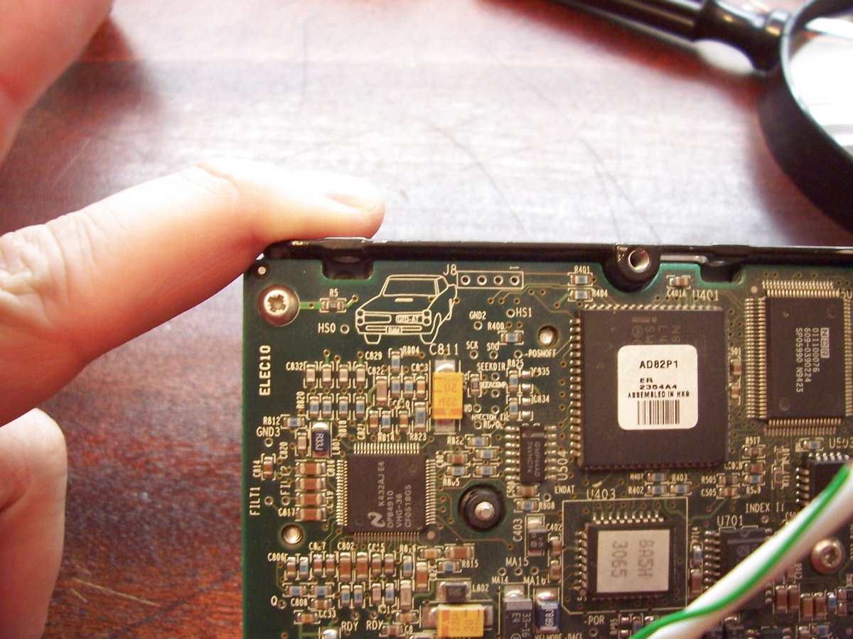
Flip the drive over and remove any circuit board mounting screws. Many manufactures use special screws such as Torx head screws. You can purchase a set of specialty screwdriver bits at most hardware stores. If you don’t have the correct bit you can usually use a set of Allen wrenches. |
|
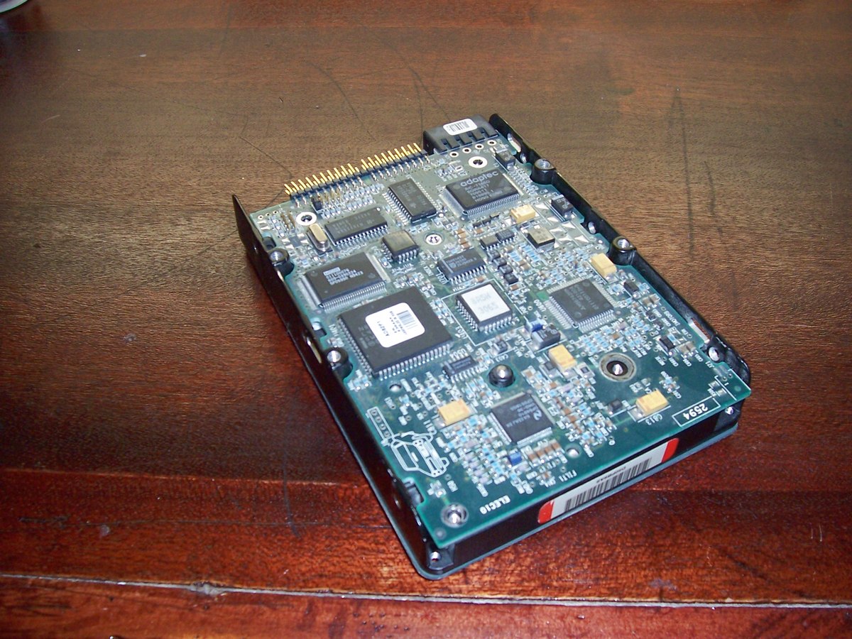
Carefully remove the circuit board and look to see how signals are transferred from the circuit board to the drive. In this case there are two thin strips (lower left on circuit board) for low current signals, and some contacts (upper center of circuit board) for motor power. |
|
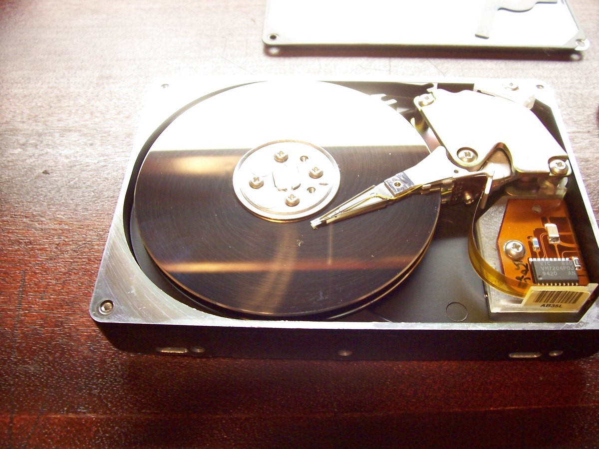
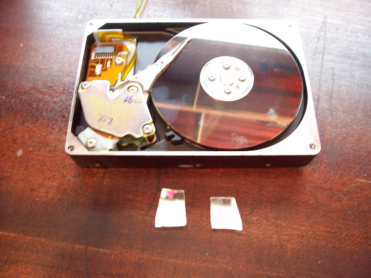
Flip the drive over and remove the screws that are holding the drive cover on. Inspect the read write arm actuator to make sure it looks like the one in the picture. The curved metal in the lower left of the picture houses two powerful magnets and a voice coil in the center of them. |

|
Next you need to find how the voice coil is connected to the drive. Look for two small wires coming out of the voice coil. Look closely to see what they are connected to. Since the voice coil requires more power than the signals going to the hard drive heads the traces are usually a bit larger. In my case the connection comes over on the two lower large traces of the flexible connector. If you have a Ohm meter it would be a good idea to meter the voice coil to make sure your stereo can power is. You should be fine with any value of 8 Ohms or greater. |

|
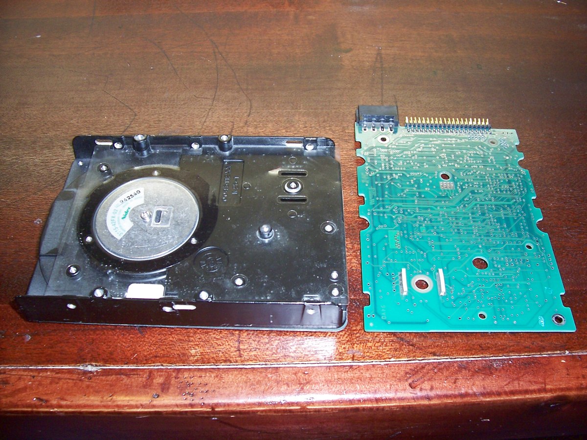
Now trace out where the voice coil wires terminate within the hard drive assemble. In my case the traces were visible on the board that the flexible cable plugged into. |
|
In the lower left you can see the two slots where the low lever signals and voice coil power is connected. At this point it would be easiest if you have a ohm meter to true out the wires you are after. In my case it is quite obvious since the pads for the voice coil is larger than the others. |

|
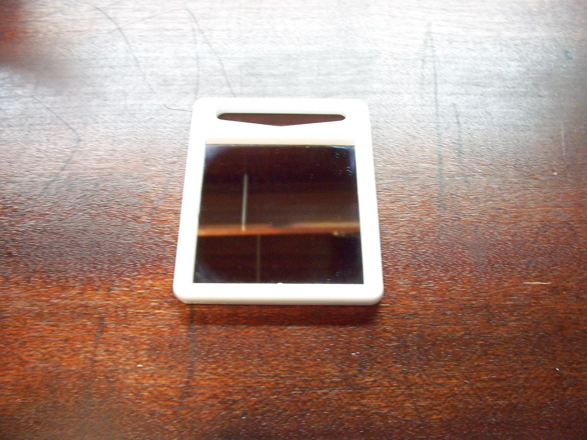
We now need a cheap mirror for the project. I uses a small two sided one that I got from the dollar store. |
|
Remove the glass from the holder, hopefully better than I did 🙂 |
|
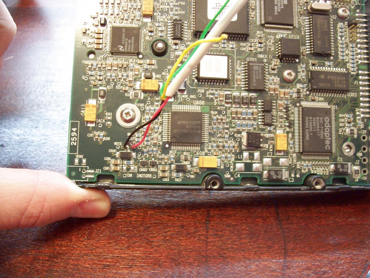
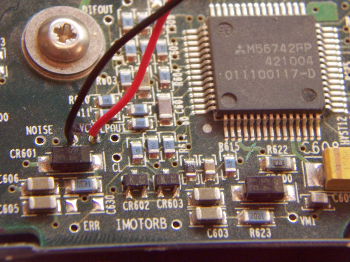
Trace out where the voice coil is actually connected to the main circuit board (control board) and solder a few wires to them. If you have an Ohm meter you should meter your newly soldered on wires and if all is good you should read your coil resistance. It is very important to make sure that you don’t have a dead short which is easy to do by accident when soldering wires that are so close together. A dead short could cause permanent damage to the stereo that will be powering this unit. |
|
The designers must have had a bit of extra time on their hands, look in the upper left corner of the circuit board. |
|
It is a good idea to disconnect the control board voice coil drive circuit from the voice coil. Do this by tracing the voice coil traces to find a convenient place to cut one of them. In my case I cut the trace where it exited the drive chip. Look between R615 and R622 (below the large chip). The mark that looks like a scratch was made with an exacto knife and cuts right through the trace. |
|
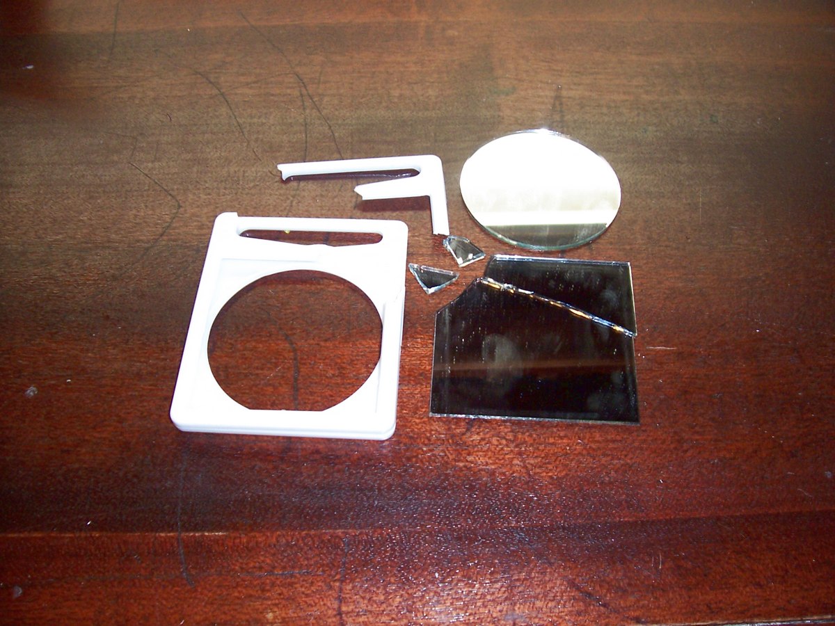
You will need two mirrors for the project. Since mine was broken already I just smacked it with a hammer to but out some pieces that I could use. I have a glass cutter but after breaking the glass when trying to remove it carefully the hammer felt much more satisfying… |
|
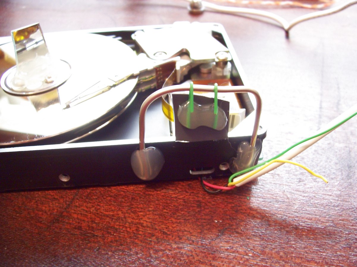
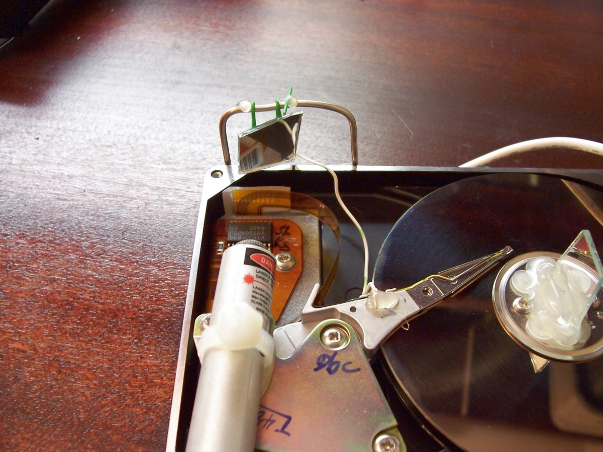
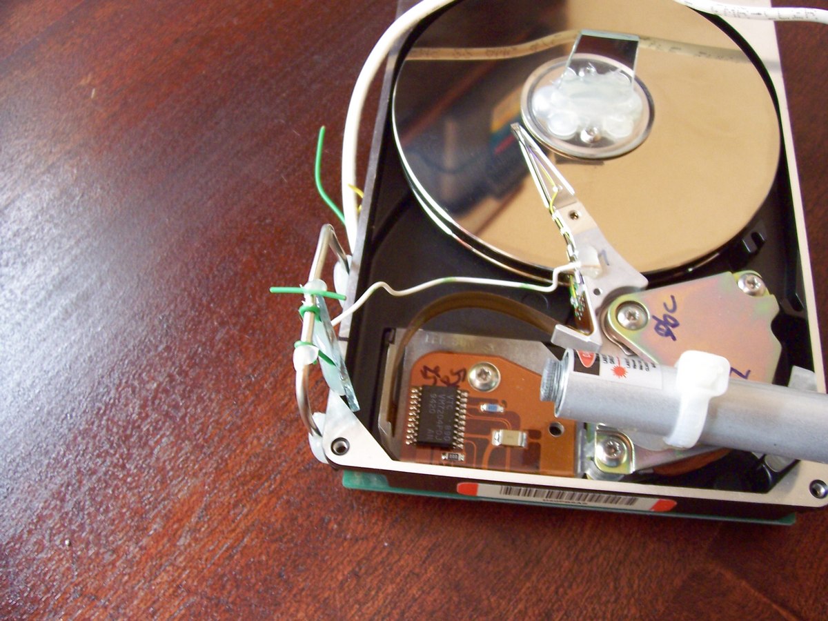
Mount the mirrors, one goes in the center of the platters. The second needs to be hung from a pivot point. I hinged mine from some bent 10 gauge wire I had laying around (large shiny wire), the green wire is 24 gauge telephone wire. Make sure you mount it in a place that will work. The laser that will be mounted has to be able to bounce a beam from the hinged mirror to the mirror in the center of the platters. Some hot glue holds it all together. Once this step is done the center mirror should turn with the drive platter and the side mirror should swing freely. |
|
Connect the read write arm to the first mirror, I used some more light gauge wire to do this. Whatever you use should have some play in it. Something that is very rigid would not perform well. |
|
The last step is to mount and align the laser. I used a tie strap around the laser body to keep the button pressed. The laser was hot glued to the hard drive. While the glue was drying I did the fine tuning, bending the swinging mirror mounting wires to have it bounce the laser light off the center mirror etc. |
Well that is about it. Now all you have to do is connect the wires that you soldered to the control board to your stereo (use an old stereo if you are not sure you did a good job with your soldering). You will probably have to put quite a large amount of power to the hard drive voice coil to get good movement. I connected one normal speaker to the left stereo output and the hard drive to the right output. I then adjusted the balance so that it was putting more power to the right side. Don’t overdrive the hard drive voice coil since you can blow it just like a speaker can blow when overdriven.
If you decide to build one post a picture of it in the Hacked Gadget Forum, I would love to see it.
Permalink
Really great! i opened a hard drive 8i dont know the brand) and its diferent it has a smaller circuit board and i can’t trace where the voice coils is connected… i cant find 2 holes like you… if you can help me can you write me to bruno_kpo_4ever@hotmail.com or add me to msn. thanks
Permalink
Since this requires you to move the hard drive platter by hand, here’s an idea for a cheap platter movement method.
Go to your local WalMart or Pet store, and pick up a cheap aquarium air pump… The cheaper the better. The pumps in these devices are
a simple diaphragm and they just oscillate at 60hz. You could attach the guts of one of these pumps to the platter with some plastic, or
spring steel and get beautiful consistent oscillations for a better looking hands free output.
Just a thought 😉
Permalink
I have an old western digital 720MB hard drive. I was trying to follow the instructions for a different drive but I’m having trouble with the wiring instructions. Do you have any suggestions?
Permalink
I have dead notebook 2.5 inch HDD and I want to to assemble the scope.
I supose that you’ll need to make the main motor of the drive spin. But how can you do that. i tried to supply the pins with 5 volt (the pins asigned for motor supply) but it wont spin. Could you pls help?
Sirous
Permalink
well, i followed all the instructions on my Fujitsu 20GB HD, but so far, i cant get the needle to move. it vibrates, and the hard drive acts as a speaker, but it doesnt move enough to move the mirror. any suggestions?
Permalink
Try moving the connection to the mirror closer to the end of the read write arm, this should give it a longer throw and move the mirror farther.
Permalink
how far should the arm rotate? mine barely makes it past 1-2mm
Permalink
Permalink
i did pratically the same thing but useing 2 dc motors
one for x axis and other for Y axis
if you have a tone generator program, you can make it form lissajous figures with the laser…
works nice 😉
Permalink
Hard drives use a brushless motor to spin the platter, you will need to alternate the current through the 3 wires, kinda like a stepper motor. It will not spin with a DC current. Perhaps a low voltage AC current will move the platter enough to work?
Permalink
Permalink
hi
where did u get the laser from
does the hard drive contain a laser or u bought it from the shop.
please email
malistani_1372@yahoo.com
Permalink
HI malistani,
That was just a gutted laser pointer. If you are interested in a laser that has leads on it already we sell them here.
http://alan-parekh.vstore.ca/product_info.php/cPath/5/products_id/35
Permalink
Permalink