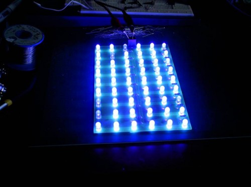
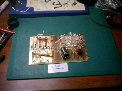
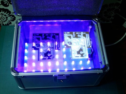
This project shows the creation of a large array of UV LEDs. They are used to expose a presensititised blank circuit board. Another common method is to use UV tubes. Alfredo has translated it to English as well as he could (English is not his first language). This is great since for some reason the good old Google translator could not do much with it. Thanks Alfredo!
"Why if we make PCBs under 160x100mm we need to use big insolators size legal or A4? We can make an insolator box little, portable,cheap and really cool. We are going to use UV leds with wavelength of 400nm that are the most indicated for our presensibilited PCBs for its high component of UV and nearest to visible light spectrum ( an important part of actinic light ). Usual 6w UV tubes seems that provides more UV power than leds UV of about 60mw, but not all power in UV tubes is light intensity, the most power is disipated as heat. We used to make the isolation box: 54 UV leds buyed from E-bay for about 15 $ 18 resistors 68ohms, 1/4Watt for 0,60 $ 1 two pole connector for about 0,85 $ 1 Electrolitic capacitor of 2200uF and 30v recover from a F.A. 1 Eurocard presensibilized PCB of 160x100mm The insolator is powered with 12Vcc. Leds goes in groups of 3 conected in serial with a resistor of 68 ohms. As the cone light angle of LEDs is 20º, we need a box that have about 80 mm of height to put the leds in a grid of 18mm. We have founded a metal box with 85 mm of height in a chinesse bazar for about 12$ that is perfect for the project. Later, we proceed soldering the leds on PCB. It’s very important that the leds are perfectly vertical to PCB.You can see this great solder job!!! After of solder process, we applied 12Vcc to PCB and… voila!!! Warning!!! Don’t see directly to the UV leds!!! We changed 5 leds that don’t brighted than others. Next we buyed a glass cutted in a form to put into Box for about 1,5$ and put a piece of foam on box cover for tight the PCB with glass for a good insolation without shadows. You can see a PCB made with this insolator box with 6 minutes of exposure. The best thing taht you can make with this portable insolator is that you can bring it at your friend’s home for make little elctronic projects. The next thing to do is a timer with LCD ,4 buttons and PWM intensity UV control for don’t flame some strange PCBs." 

UV LED PCB Exposure System


Permalink
Hello!
I’m really interested in upgrading my two sided exposure box to this kind of solution, but i have a doubt. In ebay i only can find 5mm 395nm uv leds with 2000mcd. I saw, in the original website of this project, that they recomend a 6000mcd uv leds. Can you help me by provinding links to on-line stores that sale this kind of leds? Or hints on how to work with the 2000mcd leds, if it is possible to use them? (more exposure time perhaps?)
Best regards,
Filipe.
Permalink
Hello, take a look at this page :
http://cgi.ebay.fr/100-brightest-NEW-5mm-ULTRA-VIOLET-UV-LED-7-000mcd-F-R_W0QQitemZ120021967830QQihZ002QQcategoryZ66951QQtcZphotoQQcmdZViewItem
Wavelenght is 400 to 405nm I think it is good for this project.
Yours,
Michel (from France)
Permalink
Hello.
I am interesting to build this project and i need some help.
What are the dimensions of the box that i can use?
What is the Distance between the leds and the Glass?
Can i use more or less led?
Best regards,
Lefteris
Permalink
Hello all!
Thanks Michel! But a few days after i posted i bought some leds from that same company. After some tests, it worked awsome with Positiv20 as with pre-sensitized PCB boards that i had at home.
Now, i’m waiting for the arrival of 300 leds from the same company (excelent communication – bought and agreed shipping by email in minutes) to build a
Permalink
Has anyone figured out where the Electrolitic capacitor (2200uF and 30v recover) is fitted? I have solderd alle the uv-leds and they work fine with 12v DC without the capacitor…
Have I missed something?
best regards
Gribb
Permalink
Looks like it is to be connected at the +/- indications (near where the power is attached)
Permalink
can anyone plz let me know what does 30v recover means? can i use any 2200 micro farrad electrolitic capacitor? also are these ultraviolet leds harmful to skin and eyes? if yes what material should i use for insulating box? thanks in advance
Permalink
Hey electrical guy,
Looks like that is the working voltage of the capacitor, of course higher is fine (just not lower).
UV LEDs will do harm to your eyes if you stare at them for long periods of time. As long as the lid is closed when operating you should be fine.
Permalink
I have now made a nice UV exposure boks 😀
Leds I used:
http://cgi.ebay.com/ws/eBayISAPI.dll?ViewItem&ih=006&sspagename=STRK%3AMEWN%3AIT&viewitem=&item=160079510243&rd=1&rd=1
Permalink
I have build UV LED lightbox using old flatbed scanner and 40 Kingbright L-7113UVC LEDs. These LEDs have narrow ray (+-10 degrees), it helps to get sharp shadow on photoresist even if photomask is not cling to the PCB very tight. LEDs mounted on carriage moved by stepper motor (scanner’s mechanics reused with my own controller based on PIC12F629), so 40 LEDs are enough to expose up to A4/Letter PCBs. LEDs mounted close to each other, so it provide well distributed light even with small deepness of box. Exposure adjusted by changing linear speed of the carriage.
http://forum.ixbt.com/post.cgi?id=attach:48:2184:1220:1
http://forum.ixbt.com/post.cgi?id=attach:48:2184:1238:1
http://forum.ixbt.com/post.cgi?id=attach:48:2184:1238:3
http://forum.ixbt.com/post.cgi?id=attach:48:2184:1240:1
Permalink
Permalink
Hi guys!
R u sure the resistance value should be 68 ohms? Should it not be 510 or 680 ohms? Because the current on which these leds( uv ultrbright 7000mcd – 400nm) operate is 20mA at 12V. but if we calculate, 68 ohms will give us 176mA at 12V. And does 68 ohm resistor exist? Correct me if i m wrong. Thanks.
Permalink
T2W Electronics Co., Ltd which was found in 2003 as a passive components manufacturer in China,
Our main field is concentrate on Passive Components, especially all kinds of capacitors (Aluminum Electrolytic Capacitor / Ceramic
Capacitor / Tantalum Capacitor / Film Capacitor ). Meanwhile, we also provide a wide chain of Trimming Potentiometer / Varistor .
Permalink
re electrical guy’s resistor query – the forward voltage of the LEDs is around 3.5, so adding three in series will mean that the resistor has to drop the remaining 1.5V (12- 10.5) – so the current will be 1.5/68 = 22mA (not 12/68 = 176 as you thought 🙂
Permalink
qbaxtmpvh ktxeajwfv hsyotn wdijenzrg xlmshzfwq wfsknrgyc lmhfbjan
Permalink
that capacitor is useless. since all is DC here, the only thing that capacitor would do is suck more energy from the power source when the whole thing is started. Other then that, great project! i am going to create one myself!
Permalink
See UK Elektor magazine, May 2006.
Uses standard Eurocard pcb, 24 x Kingbright L-7113UVC, even a PCB (download from their website under ‘magazine’).
1N4007 in series for input, 120R resistor between each pair of LEDs & ground. Polish & varnish board to aid reflection – or paint white.
Smaller 1/2 eurocard size using 12 LEDS.
6 minutes for exposure time at distance of 80 mm.
http://www.elektor-electronics.co.uk/magazines/2006/may/uv-led-light-box.58233.lynkx?tab=2
Permalink
I made this proyect myself bu I struggled finding a proper box for it. Finally I come across a 1.6L plastic box from http://www.reallyusefulboxes.com/.
The PCB fits nicely and the dimensions are just perfect for it.
If anybody wants to have a look at the finished proyect I took some pictures and uploaded them to http://freespace.virgin.net/big.jesus/index.html
All the merit goes to the original authors at RaDiKalDeSiG.
Cheers 🙂
Permalink
One thing I’d like to say about your (WaKaRu) exposure device: Shield it so the UV source cannot be viewed when the device is active. That transparent box, although cool looking, makes me think you are asking for eye cataract. Cover it in duct tape or something, just don’t leave it transparent like that! These UV LEDs are not toys, but a little sneaky eye killers at best…
Permalink
Thanks for the health & safety comment gedit, I will certainly do.
Permalink
thanks for information….
Permalink
Are you guys using fused silica or normal window glass? Normal glass usually absorbs too much of UV radiation, although I’m not sure if this is a problem around 400nm, or only for shorter wave lengths.