
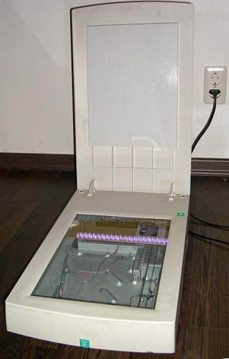
Sapa responded to this article with an example of his creative PCB exposure system made from an old computer scanner.
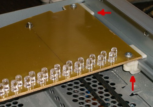
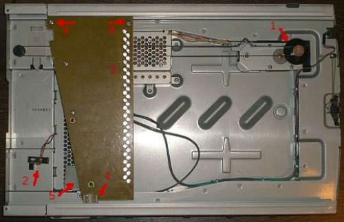
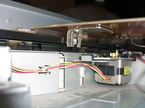
“I have build UV LED lightbox using old flatbed scanner and 40 Kingbright L-7113UVC LEDs. These LEDs have narrow ray (+-10 degrees), it helps to get sharp shadow on photoresist even if photomask is not cling to the PCB very tight. LEDs mounted on carriage moved by stepper motor (scanner’s mechanics reused with my own controller based on PIC12F629), so 40 LEDs are enough to expose up to A4/Letter PCBs. LEDs mounted close to each other, so it provide well distributed light even with small deepness of box. Exposure adjusted by changing linear speed of the carriage.”
Permalink
What is the exposition time you use with your Exposure Scanner?
Permalink
My photoresist (Cramolin POSITIV spray) well exposed with carriage speed = 2 cm/min.
Permalink
Hi,
Any idea where we can find the original article. I would love to build one of these and would appreciate additional info regarding, power source & circuit used for the LED’s, the HEX code for the PIC12F629, etc.
Tx, Conroy
Permalink
Hi Conroy,
Sapa was the creator, his site is listed above. I don’t believe there is an original article (just the pictures that are shown above). You could go to his site and contact him from there.
Permalink
Hi Conroy,
I didn’t write an “original article”, I only wrote about it on forums. But I may publish it in my journal with schematics, PCB and firmware if it is interesting for you. No problem.
Permalink
Hi Sapa,
Tx for your response, much appreciated. I am confident that there are lots of other people interested as well. You would be doing all of us a great favour !!
Permalink
I have written some brief draft and will update it from time to time: http://sappa.livejournal.com/19579.html