

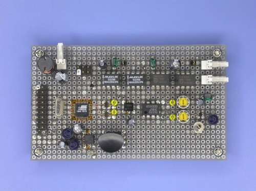
This DIY Audio Spectrum Monitor by a Japanese engineer looks and works great, there are full construction details and code available on his site. You have to watch the video, it’s very impressive.
Video after the jump.
“This is an experimental work to monitor a spectrum pattern in radio band, and is a continuous project from Audio Spectrum Monitor. To analyze the spectrum of an input signal, I chose an Atmel AVR microcontroller that used in the Audio Spectrum Monitor to process FFT. When think it easy, it can be thought that sample an input RF signal directly and analyze it will do. However, you will able to recoginize that there are some techinical difficulties from following reasons.
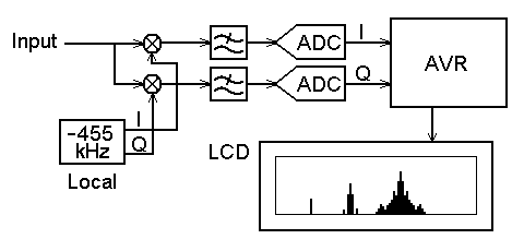
In this project, an intermediate frequency signal from mixer output of an AM radio (fC=455kHz) is used as an input signal. It is converted again down to zero hertz in complex signal, so that the signal path, mixer and local oscillator, must be composed for complex signal processing. The complex signal is expressed in two wire IQ signal, the real part corresponds to I signal and the imaginary part corresponds to Q signal. The arithmetic circuits for IQ signal are realized in method of complex arithmetic. For example, a mixing circuit for IQ signals requires four multiplyers and two adders from the formula:
(a1+jb1)(a2+jb2) = (a1a2-b1b2)+j(a1b2+a2b1)”
Thanks for the tip Dick
|
|
Permalink
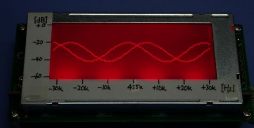
Looks really nice, any guesses on the nature of the screen? Looks like a standard LCD with red LED backlight, but I could be wrong.
Permalink
That is exactly what it looks like Nick.
I wonder how easy this would be to program for a use with a PIC, and also how easy it would be to modify the analyzer range.
Permalink
NGinuity,
It all depends on what spectral resolution you want. The really neat thing about this design is that it uses a mixer to shift the carrier band frequency down to something slow enough to allow a normal ADC to sample it. This can be done with pretty much any frequency. Depending on how fast your PIC can do FFT, you will be limited to the frequency resolution around the center frequency of interest, so the choice is really up to you. You may also have some luck with specialized DSP chips that have dedicated hardware to performing FFT.
Permalink
Here are the specs. for the LCD he used.
http://elm-chan.org/junk/s9894/report.html
Permalink
Permalink
Nick, thanks for the reply. I am actually looking for something to detect interference with. The accuracy doesn’t have to be all that great, but I would like to at least be able to differentiate transmitter harmonics from random noise interference. I was looking at a project called the “Scotty Spectrum Analyzer” that would give me 1MHz to 1GHz coverage (I think), and it was just a computer controlled frontend where the sampling took place. I have the Microchip rep wrapped around my finger right now, so I would imagine that I can get just about anything I needed.
From what you are saying, (I haven’t actually looked hard at the specs yet), but it sounds like the design is using a mixer as a frequency divider? I see where the accuracy comes in to play when you get into higher frequencies.
Permalink
Permalink
NGinuity,
Glad I could help! Firstly, the mixer is not “really” a frequency divider. The better way to think about it is when you are comparing two sinusoids of the same frequency that both have an unchanging phase in time. If you compare the average ratio, you will get a constant value for all time (sampling with a slow ADC compared to the signal is like an effective averaging). Now if one of the frequencies is slightly different, you will get something called beats. This happens because at a given point in time, the signals will be completely in phase, and then some later point in time (dependent on the difference in frequencies) the signals will be completely out of phase. So when the 455kHz signal is mixed and averaged with the incoming signal, the DC amplitude is the ratio of the incoming 455kHz signal to the local oscillator signal, and the FFT that is done tries to determine the beat frequencies which can then be converted into incoming signal frequencies around the 455kHz local oscillator. In this sense, if you have a programmable oscillator, you can *theoretically* apply this technique to doing the same king of analysis around almost any frequency, but be aware that there are some tricky things. Firstly, since you are trying to look at harmonics, employ some kind of windowing/tapering algorithm for the FFT that you end up implementing. If you just take a chunk of your time-series data and analyze it directly, you will get some harmonics around center frequency that are not really there. Secondly, as you move into the higher MHz range, more and more care must be taken to account for the non-ideal properties of various circuit elements. Hope this helps!
Permalink
Thanks Nick, It certainly does clear a few things up. Didn’t really get a lot of that RF theory in college, but I am making up for it with Ham Radio 🙂 Seems simple enough to go that route. I was confused earlier, but now reading it more (with less beer and more coffee), it just looks like the mixer is functioning as a downconverter of sorts. I have seen double balanced mixers accomplish this quite effectively, with somewhat effective results (And, I might add, I have used that SA612A mentioned in a recent project with great success). It makes perfect sense to slow the frequency before you sample it with an ADC. Seems to me it would be more cost effective that way as well. It should work for the accuracy I need.
Permalink
Instead of the LCD output display, how can you drive it on a Windows based computer via USB connection.
What software would you go about using to show the real time output signal ( LabView, Simulink, etc.)
Permalink
Hey a great project,I am no expert but wanted to duplicate the project but unfortunatly could
not down load the code for the AVR and kept getting corrupted files.Could anyone suggest
a secondary source?
Permalink
Hey Nevin,
Is this the file you are downloading?
http://elm-chan.org/works/rsm/rsm.zip
It downloads and each file opens fine for me…
Permalink
thanks Alan,it is the same file that you mentioned it downloads,but I still cannot open it.
I used winzip & enzip to try to unzip the file.It keeps telling me it is an
invalid file? is some other software to be used ? could you suggest it to me?
or could I download a unzipped version from someware.
Permalink
Nevin,
Files have been emailed to you.
Permalink
In what order do you load this files to the Atmel chip?.
This looks like a great add-on device to a monitor radio.
Permalink
how could i make one with different color LEDs?
Permalink
can anyone give me a link or copy of the source code for this project… that would be much appreciated…