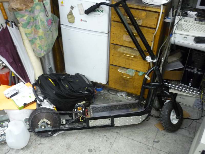
Check out the Electric Scooter MK-1 Build Log, Dane from transistor-man.com has done some cold weather testing and it looks like it works quite well!
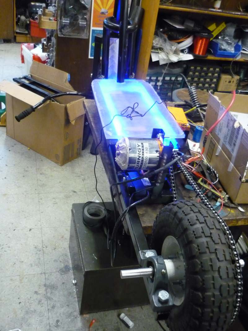
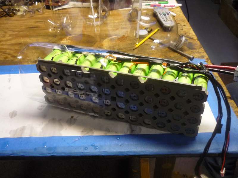
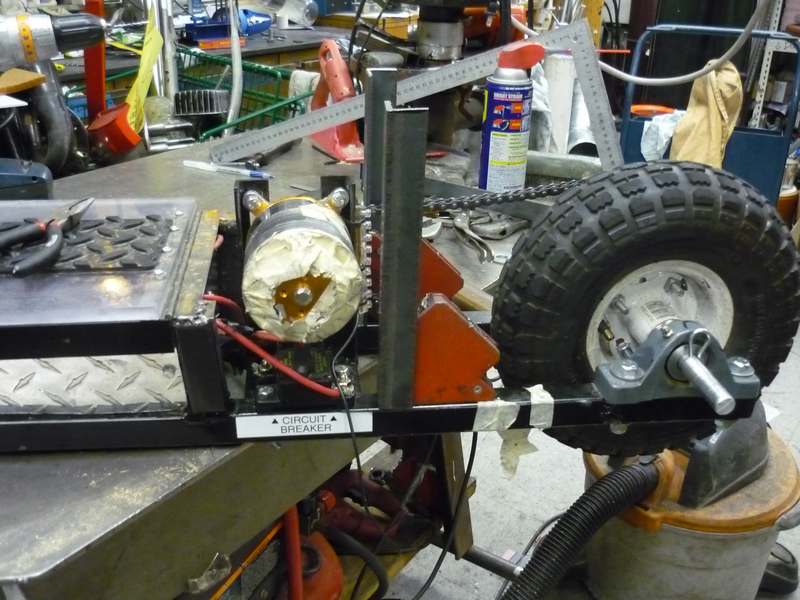
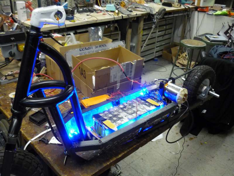
“The electrical layout for the MK 1 scooter is fairly straightforward. Everything starts from the 12S 4p cylindrical battery module. A Cooper Bussman 120A circuit breaker sits between the battery and the rest of the scooter. Note that, while there are a number of DC circuit breakers out there, VERY few actually tolerate vibrations. I found this out the hard way when I started using [link]. The first hint of vibration and the breaker tripped, which, made it fairly hard to use. The headlight I chose is a fairly awesome 30W led setup with a 30 degree beam path. It has an onboard dc/dc, but unfortunately its max input voltage is 30V. I used a 40W dc/dc to bring the module voltage back down to 12v DC, which is useful for driving the LED assembly as well as 12v accessories (if I opt for adding a sealed 12v cigarette lighter outlet). Finally a linear regulator feeds the 5v logic for the three phase sensorless controller and throttle assembly. “