
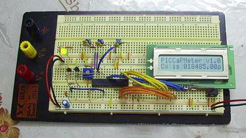
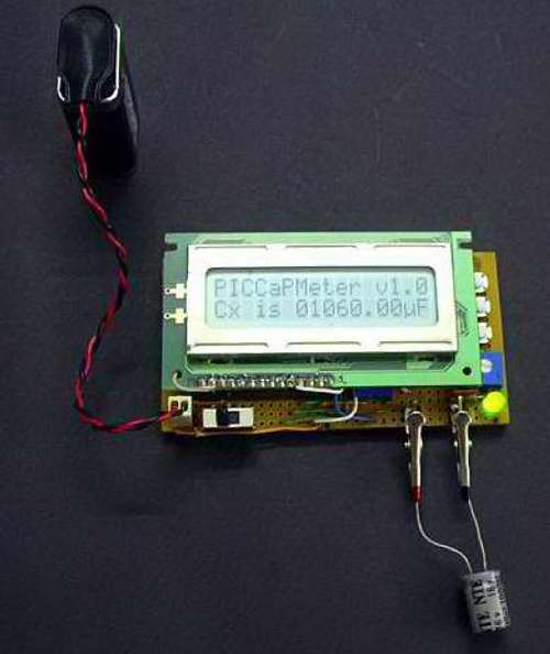
Why buy test equipment when you can make your own? Edwin made a capacitance meter using a PIC16F873A as the brains. If you want to make your own there is code and a schematic provided on his site.
“This is an autoranged version, which means one does not need to adjust the range settings. Furthermore, the measuring range is quite large, from 5pF all the way to 2600uF. It is all taken care of by the PIC16F873A inside the circuit. The capacitance meter begins by discharging the capacitor fully. Then it charges it and waits until the voltage across the capacitor reaches 0.632Vcc. The time is then captured and the capacitance is computed using Tau = RC. A 16 bit division routine written by Andy Warren is used for this project. The result is then displayed on the LCD. The process will then repeat itself every subsequent 0.255s.”
Permalink
Nice. I had to do something similar for my Microprocessor design class, except I had to use a Motorola 68HC11 instead of a PIC :-/
Permalink
I do need to give instructions on how to setup a moldering laptop as a web server. Geocities has turned off his website. 🙁
Permalink
The schematic on his site is incomplete and extremely vague. He fails to mention values for C 3-5 and the designation CX for the cap being tested wasn’t clear. Also, the functions of R2 and R7 were not labled (callibration and lcd contrast, respectively.)
The source code is extremely well commented, and will help anyone with the building and use of the circuit.
P.S. Meval: Geocities limits the bandwidth sites can use, resetting every hour or so. Try back later, his site is up right now, but thanks to the publicity of Hacked Gadgets, enough people went there at once to excede that limit.
Permalink
Good eye Eric,
Probably done the same way I do mine, get the circuit working then document it… I am sure Edwin will fill us in as soon as he has some time. 🙂 Too bad Yahoo doesn’t provide a bit more bandwidth.
Permalink
nice design.
I am confused with the voltage comparator that controls teh time when the Cx capacitor charge reachs the 0.632VDC..
It looks to me is using a voltage comparator like the one provided by a 16F628 as an example.
But I can not find a VOLTAGE comparator function on a 16F873A.
thanks
juan
Permalink
I agree with Erik that the designation Cx is not very clear but unless the design was recently updated it does indeed state that C3-5 are debounce caps of ~470nF and that R2 and R7 are 10K potentiometers in the design notes. But like I said This very well may be an updated schematic from the one Erik read. Still a great little design.