
This Picaxe microcontroller project looks great, there is lots of technology packaged into that tiny ping pong ball. Have a look at the PongSat initiative for more information on the purpose of the device.
"A PongSat is an experiment that fits inside of a ping pong ball. These ping pong ball ‘satellites’ are flown to the edge of space by balloon or launched in sounding rockets.The PongSats are then returned to the student. It’s an easy and inexpensive way to get students excited about science and engineering. There are endless possibilities for experiments that can fit inside a ping pong ball. PongSat’s can be as simple or complex as you want them to be. Experiments can be as simple as comparing how high a ball bounces before and after being exposed to vacuum. The PongSat can carry seeds to see if exposure to cosmic rays effect their growth. Several small inexpensive computers and other electronic can fit inside a PongSat. These can be used to create a wide range of experiments. Whether carrying a marshmallow to see if it puffs up in the vacuum of near space or an entire sophisticated satellite in miniature, PongSat can create motivation, drive and passion in the classroom.
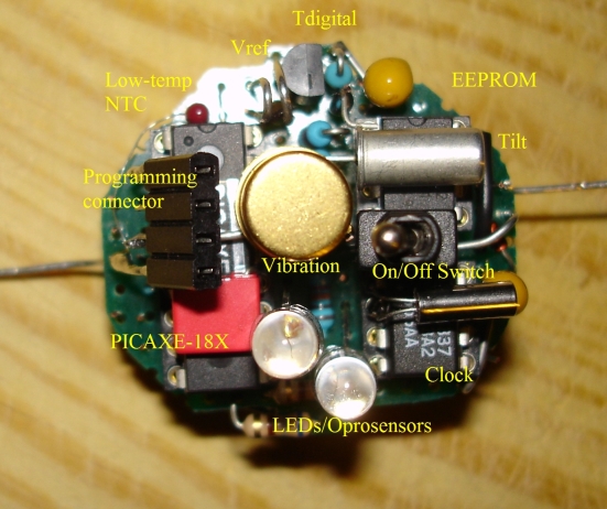
The two sensors that gave us some extra work were the tilt sensor and the use of LEDs as optosensors using the 18X output pins reconfigured as inputs.
Firstly, the tilt sensor when in the on state appears somewhat surprisingly to act as a vibration sensor, therefore it does not really register tilt. This problem was easily solved by dividing the measurement interval in short ones, register the number of changes per short interval (using the COUNT command) and then define a change in tilt as a difference between one state (0 transistions) and the other (one or more transitions) when comparing the current interval with the previous one.
The opto-LEDS testing happened in two stages. First Output 6 and 7 had to be redefined as ADC inputs. This is done by first enabling them as inputs, and then (after a waiting period to allow the incident light to discharge the reverse-charged LED) to configure and enable the ADC module and finally performing the conversion. Since a READADC10 command must be simulated by a few PEEKs and POKEs this requires considerably more time to execute. This fact, and the relatively low impedance of the input when the ADC module is enabled, causes the LEDs to be discharged completely before the read is done. As a working remedy I added a 10nF capacitor in parallel with the LEDs (This is not needed when using standard ADC inputs with READADC10). I will publish the codes for enabling the outputs as ADC inputs in the code snippets section (maybe hippy is willing to refer to it in his SFR usage thread)."

Permalink