
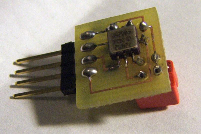
David from Volunteer Lab Rats is playing with his new ADXL202 Accelerometer. He documented the results so that we can be a few steps closer to getting it to work when we rig one up.
"The board is supplied with +5v and ground. There are two output pins on the board. They each output the square shaped signal seen on the picture below. The duty cycle of the signal corresonds to the acceleration in the X- and Y- direction. The duty cycle grows when the accelerometer is moved in the one direction, and shrinks when moved in the opposite direction."
Permalink
Not to spam, but almost the same thing here:
http://www.machinegrid.com/content/view/59/114/
and here:
http://www.machinegrid.com/content/view/53/111/
except this one has it on a PCB. awesome work anyway Labrat.
Permalink
Thanks bluehash,
Looks like the same basic thought processes were performed here! I can see why those small adapter boards are getting more popular.