
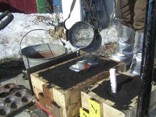
Our friends has just finished the next step of the Suzuki Electric Bike build. You may remember the last step which was the making of the gauge package. I found this process very interesting since I have recently purchased a CNC kit which I will be putting together as soon as I have some spare time. In the past I have seen many processes of making parts but I didn’t think you could pour aluminum directly into a mould that has an internal foam part. Have a look at the video below for a great step by step.
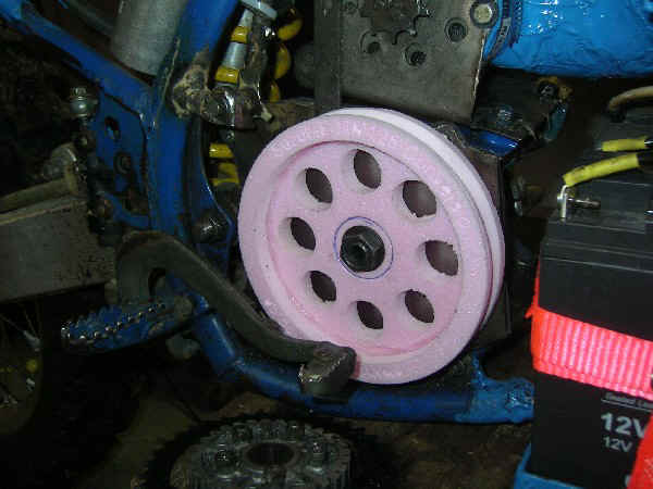
“The EPS-foam patterns are packed into flasks with foundry sand and a single pouring spout (or sprue). This is a sacrificial molding procedure, meaning that the foam patterns are consumed in the casting process. So if things go wrong, it all gets repeated, starting with machining new patterns.”
Permalink
Nice way to recycle old hard drives 🙂
Permalink
Yeah, but recovering the data can be difficult 😉
Permalink
Looks very involved.
Permalink
this is nice, i wish i lived close to these guys
Permalink
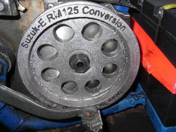
Traditionally, “Lost Foam” casting is done for parts that need internal cavities and channels that can’t be machined or cast any other way.
The GM plant in Massena NY made cylinder heads for years this way. They would cast styrofoam parts and glue them together into complex shapes with a quarter of a sprue on the end. Then they’d glue 4 sets together and dip them in and out of a liquid ceramic then let them dry. Then they’d set them in a bin and pour and vibrate loose sand all around the part to provide support to the ceramic shell. The whole piece would be filled with molten aluminum or steel.
The ceramic coating was porus and the vaporized styrene would be pushed out either the sprue or out the coating and into the sand.
After a few minutes to set, the part would be removed from the sand and quenched. The ceramic coating would flake off and leave you with 4 cylinder heads that could then be cut apart and machined where they needed close tolerances. The ceramic coating would pick up all the fine detail from the original part and the sand would keep everything from moving.
If you’re ever doing engine work and see a surface that looks like styrofoam, it’s because at one time it was.
I did this myself one time and the result was pretty impressive.
Permalink
Looks good, but I thought the “lost” (wax/foam) process of casting required a vent, as well as a pour sprue. Also his large pulley is a little off center. You can see it when it spins up.
It was nice to see such a well done casting video.
Permalink
Pouncer,
The sand is very pourous and the vapourized styrene vents into the sand,
but, Yes generally there is a second component off the body of the thickest part of the casting called a Riser.
The riser is sized to slightly thicker than the thickest portion of the pattern.
It’s purpose is to act as a resevoir of liquid metal and be the last element of the pattern to solidify.
This ensures that the Shrink Defect is located away from the physical casting.
I’ve been in Veg-Mode since posting this espisode, but will check for the Gear-Box Pulley being off center.
It’s deceptive because the pulley does have a slight lateral wobble,
but I don’t think that it could be off-center, the Idler is flailling about
because of the wonky smaller drive pulley…
Permalink
i would put it in cold water to make it stronger why he did not? 😉 B-)
:-bd
Permalink
Mikheil,
The castings were dumped into the snow bank behind the wheelbarrow…
But these castings really aren’t going to benefit too much from
any sort of “Freezing of the Grain Structure” as they are just
Pulleys…
Permalink
I’d hope that you machine or otherwise smooth out the groove in the pulley so the as-cast surface doesn’t grind the drive belt to bits.
Permalink