
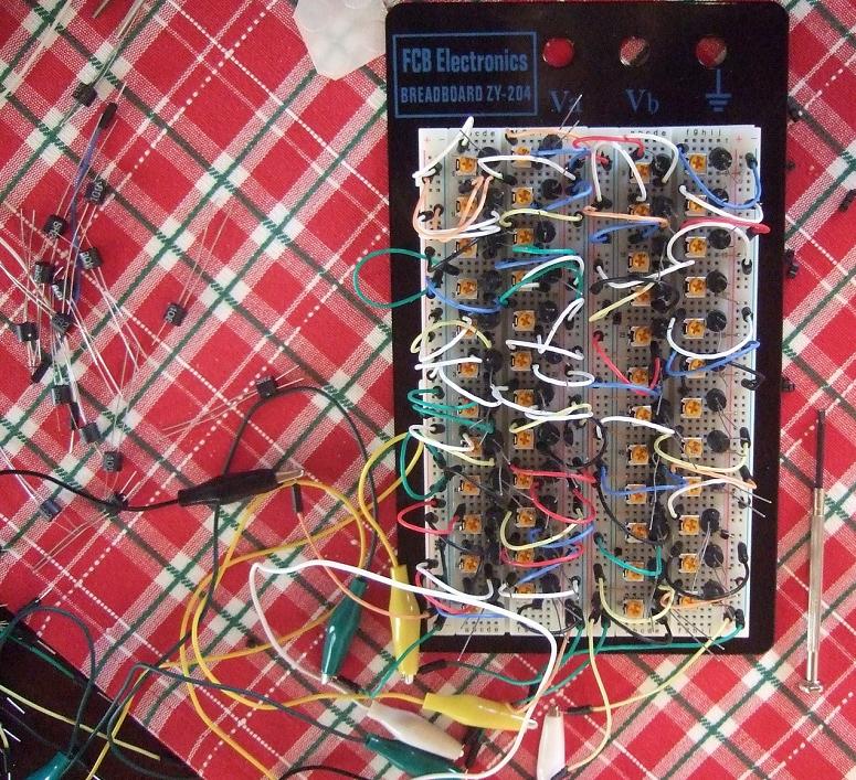
I remember when taking electronics in college it was mentioned that you could order standard transistors, or you could order matched transistor pairs for high end audio use. A pair of transistors that were matched would work in perfect unison since even devices out of the same batch will have some slight variations. Have a look at the image below for an example of testing a ton of devices only to select 2 pairs of the best matched ones. I had never heard of a passive attenuator before but we all can relate to the eventual problems of an audio system that could use this technology. Typical audio systems use a potentiometer to adjust the audio level, internally there is a wiper arm that moves across a resistive element. When dust and dirt build up inside this device you will have a crackling effect when operating the device. The designer, George Stantscheff also sells them, but at $400 USD I will stick to my more conventional system.
Have a look at the full article which includes a schematic to build your own.
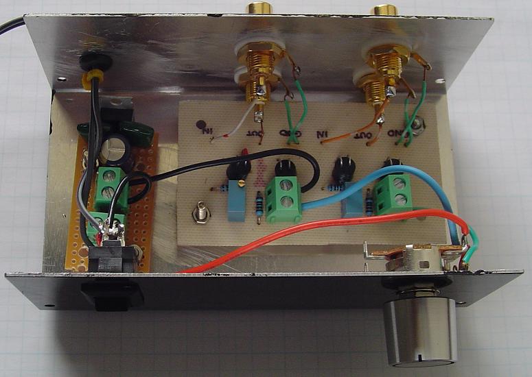
"The operating principle of the optocoupler is fairly simple. As the intensity of the LED varies, so does the internal resistance of the LDR (resistance decreases with increasing light). So in the case of the Lightspeed Attenuator, we change the volume (resistance) by changing the intensity of the LED. By using a series and shunt combination of optocouplers the attenuator can be configured to produces a constant input and output impedance, regardless of where the voltage control setting is.
The following will required to build a Lightspeed Attenuator.
- 5 VDC power supply.
- 100k dual log or linear potentiometer (quality does not matter as this only controls voltage and not the audio signal)
- Four 100 Ohm 1/4W resistors
- Two 1k to 5k multi-turn potentiometers
- Two matched pairs of Silonex NSL-32SR2 Light Dependent Resistors (LDR)
- Wire
- Four RCA Jacks
- A suitable enclosure
- Miscellaneous Hardware: knobs, feet, switches …"
Permalink
Hmmm… sorry to say this but this approach will add A LOT of noise to the audio signal. Better go with a standard pot actually… But nice idea with the constant input/output impedance.
Permalink
Actually there is NO noise. Thats one of the best things about it. No noise and no coloration. The LED can not be heard in the signal and the signal passes through the resistor NOT the LED. The LED gets power only… that has been passed through a 100k pot. The 100k pot does not see the signal either as the signal, again, does not go through it, only through the LDR.
This will smoke your TVC. Just try it.
Uriah