Â
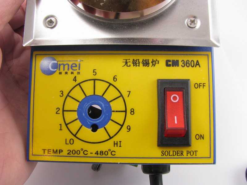
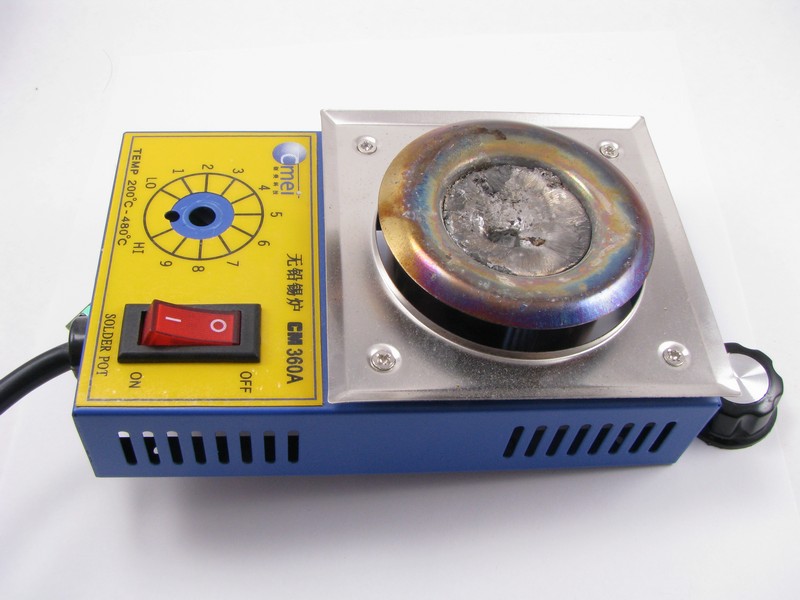
I ordered a cheap solder pot from Ebay a few months ago. I didn’t want to spend a fortune since I will only need it 5 or 10 times a year, just to take care of the jobs where using a soldering iron to tin a bunch of wires would be a pain. I had used it 4 or 5 times prior to this review and was very surprised at the quality of case construction, look and feel of the controls, and the speed at which it could melt solder. The only thing I would have liked is the power cable to exit the rear of the case and the on off switch to be pushed up to turn on. As I write this I am thinking the easiest way to solve all of these problems is to have the text on the label printed upside down so that the temperature dial, on/off switch and power cord were naturally positioned on the top. I bet that the guy who designed the case and physical layout was not the same guy who designed the label.
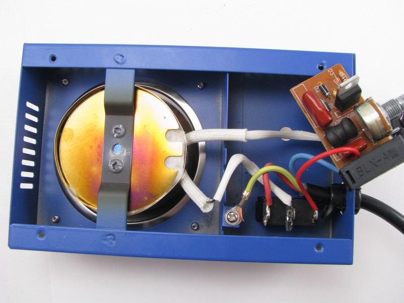
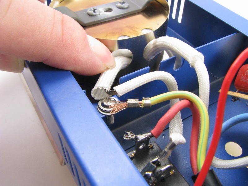
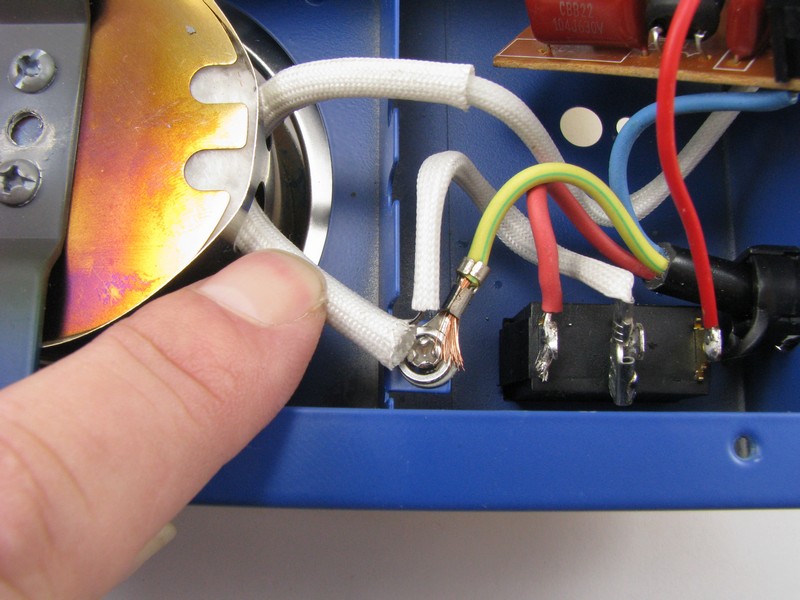
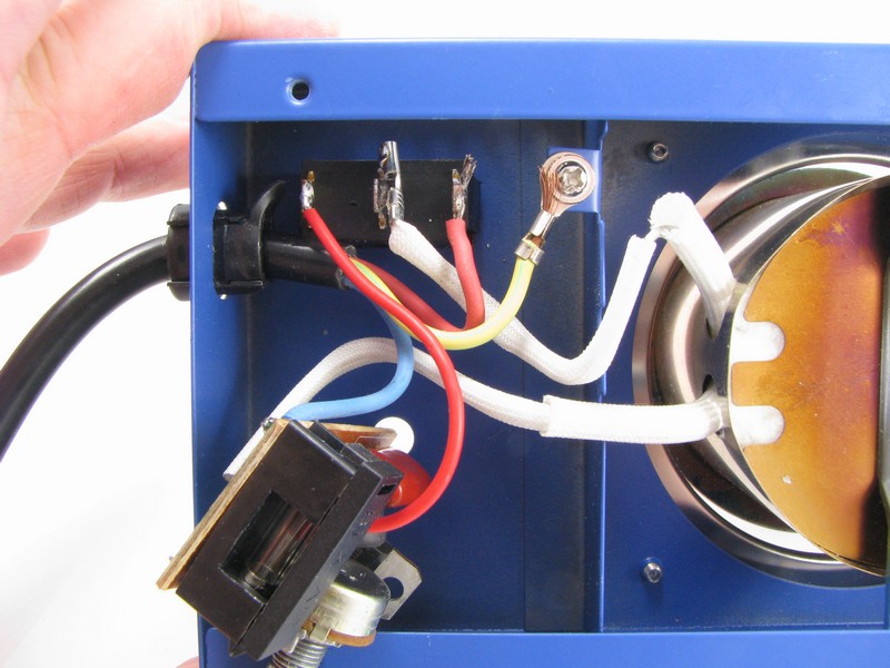
I was expecting to be pleasantly surprised at some nice build quality on the inside, but once the cover came off I lost some faith in the unit. I can see that this was assembled in a hurry like lots of other Chinese products. There is some heat resistant insulation covering the feed wires for the heating element, as you can see in the pictures and video a small sleeve should have been long enough to safely nest itself under the larger sleeve but in this case the wire was too long which left the insulation too short and exposing one of the conductors.
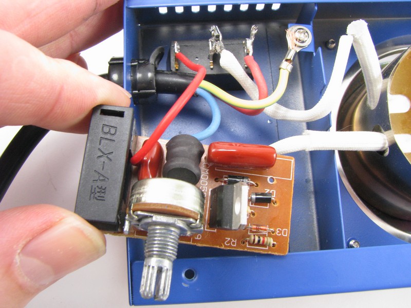
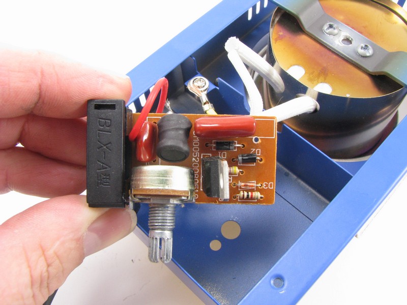
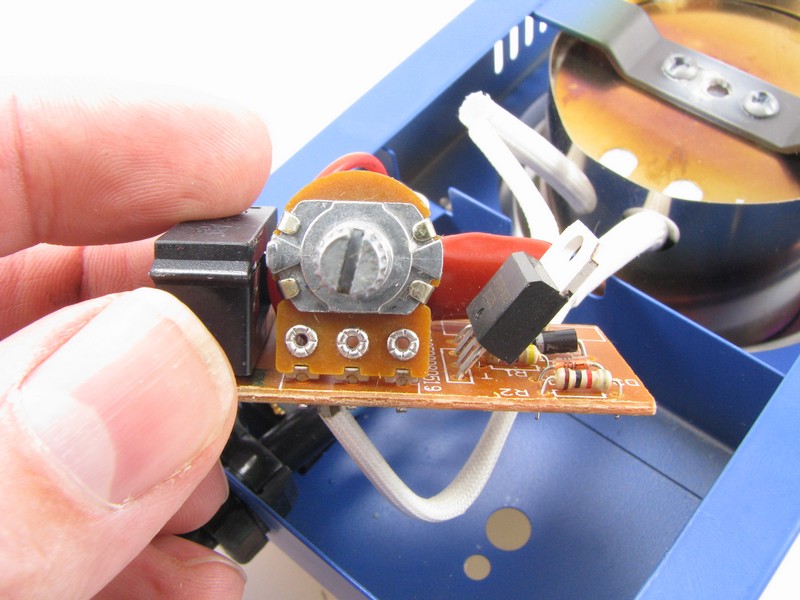
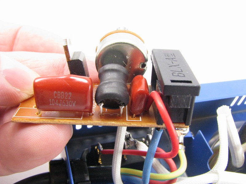
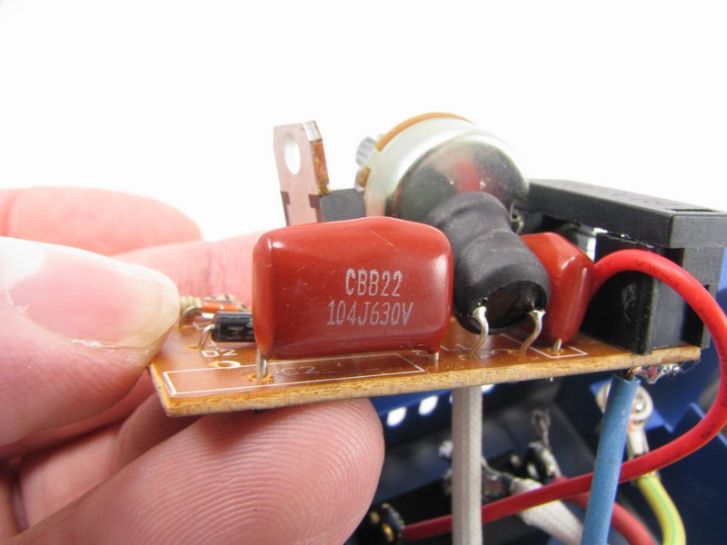
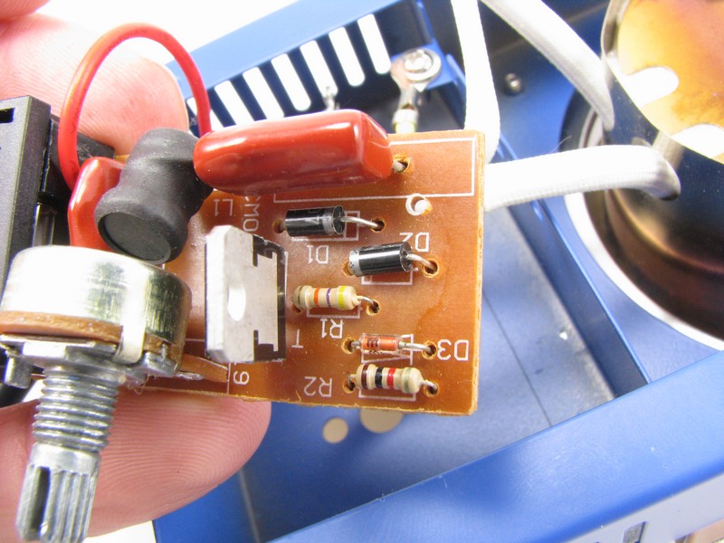
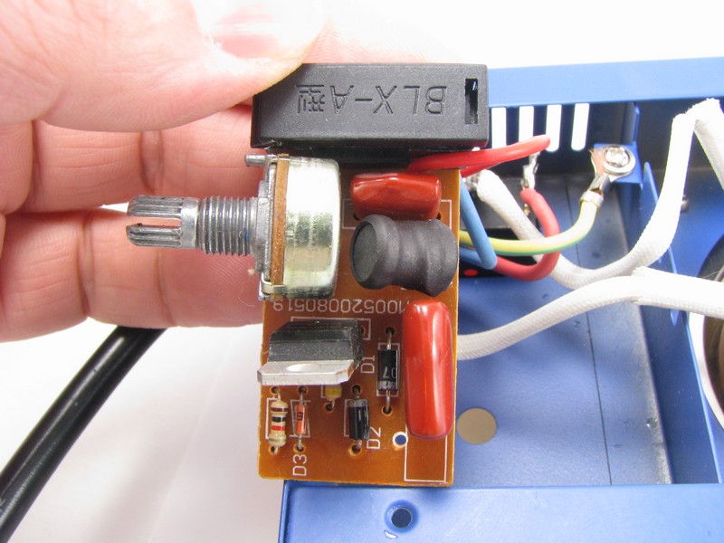
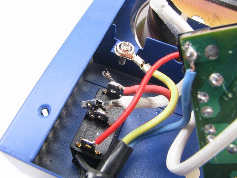
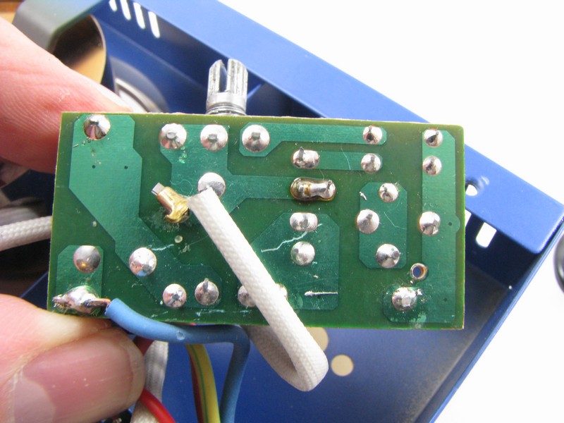
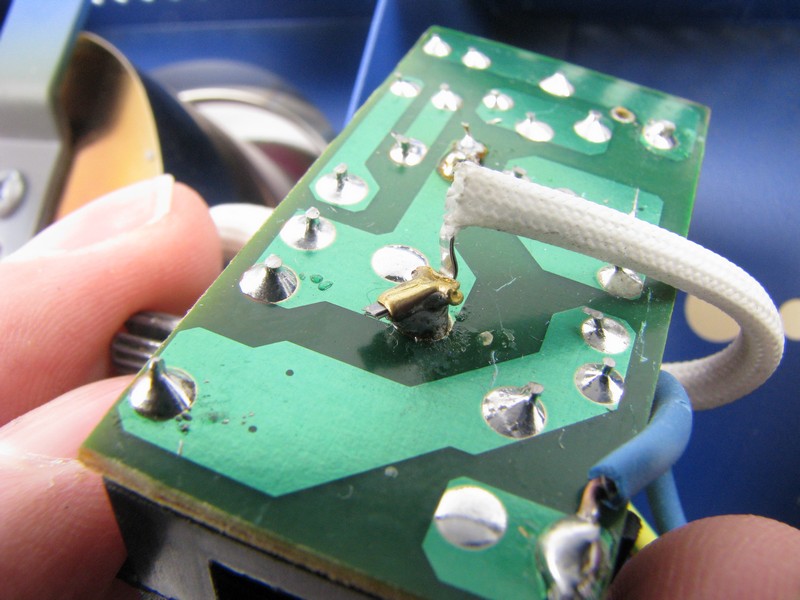
 There are some very poor connections of two very important wires to the small control board. One is the live feed direct from the plug, it is just soldered to the rear of the board onto the fuse holder solder point. It looks like originally it would have been through hole mounted from the front of the board into the same position and a smaller fuse holder (or solder in fuse) would have been used. If this wire comes loose and brushes against the inside of the case you will see a light show for a few seconds before your house breaker trips.
The other very poor connections were on both ends of the heater. There was a push on lug that was poorly soldered to the center terminal of the on/off switch. After the review a small wiggle was all it took to pop it off. When pushed onto the terminal the height of the lug interfered with the back panel, the simply solution was to simply fold the connector over on itself. The other heater connection was to the control board and this was also simply tack soldered to the back of the board just waiting to vibrate loose, looks like this connection also had a lug on it at one time but the lug was simply trimmed to a small nub which was the part soldered to the board.
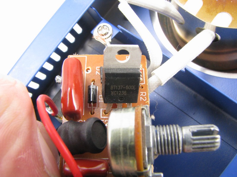
If anyone is interested the triac used in the design is a BT137-600E. There is line voltage connected to the potentiometer which feels wrong to me but with a quick glance at a similar product, it looks like you can put 250 volts on many of these little pots (such as this one [PDF]). I guess I have seen too many loose adjustment pots with missing knobs which would make me think twice about adjusting them if I knew there was serious voltage on the wipers of the pot.
I also saw a problem with the switch wiring that wasn’t there (in the video). Many of these switches have a common terminal in the center, when the switch is flipped up the center and lower terminals are shorted and when the switch is down the center and upper terminals are shorted. In this case when the switch is in the off position there is no connection between any of the terminals. When moved to the on position neutral is placed on the center terminal which has one of the heater leads attached to it and also an internal lamp connection. The hot for the lamp is connected with a jumper from the fused side of line voltage on the control board.