
With some free samples from Maxim/Dallas you could build this on the cheap.
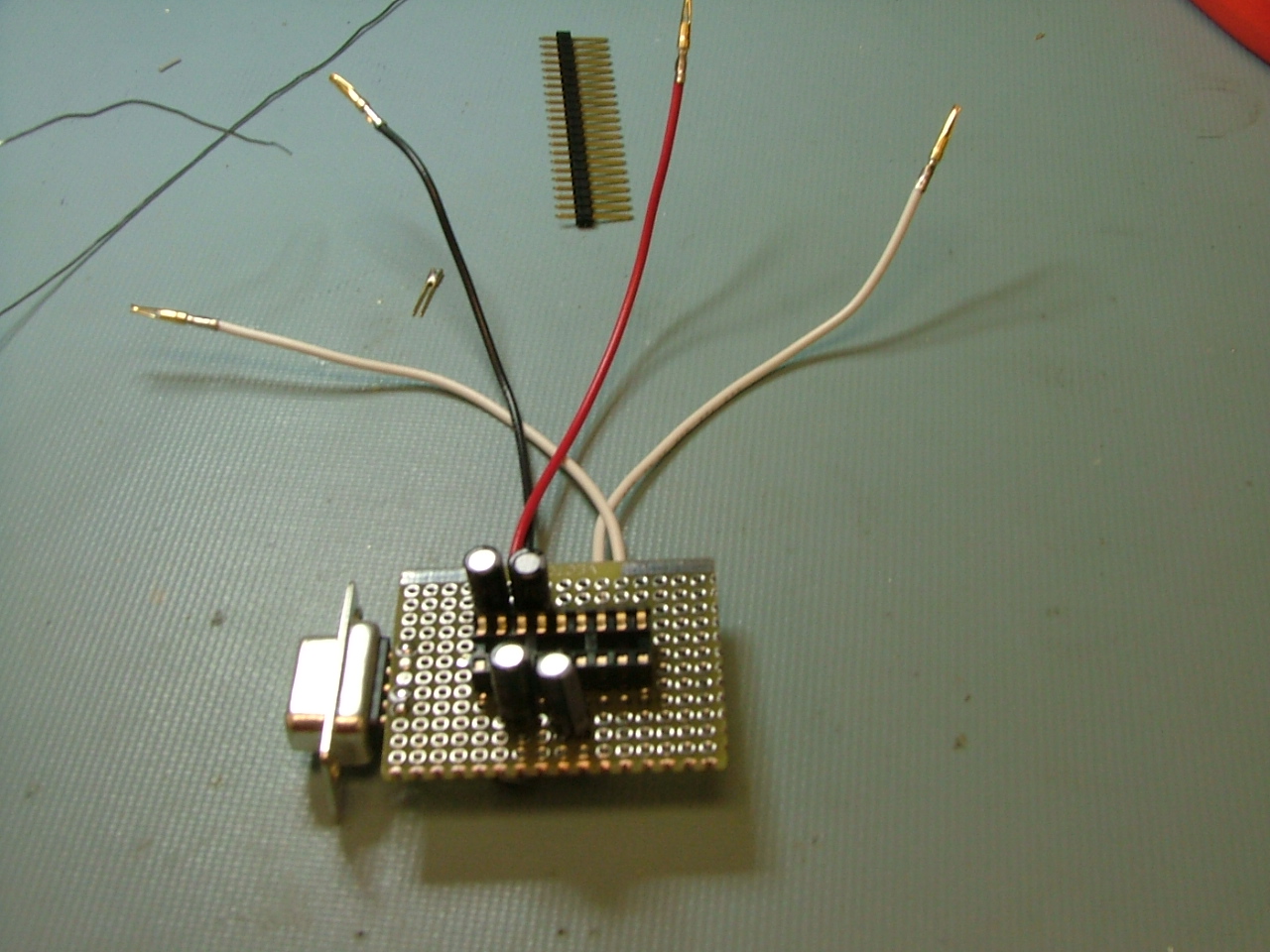
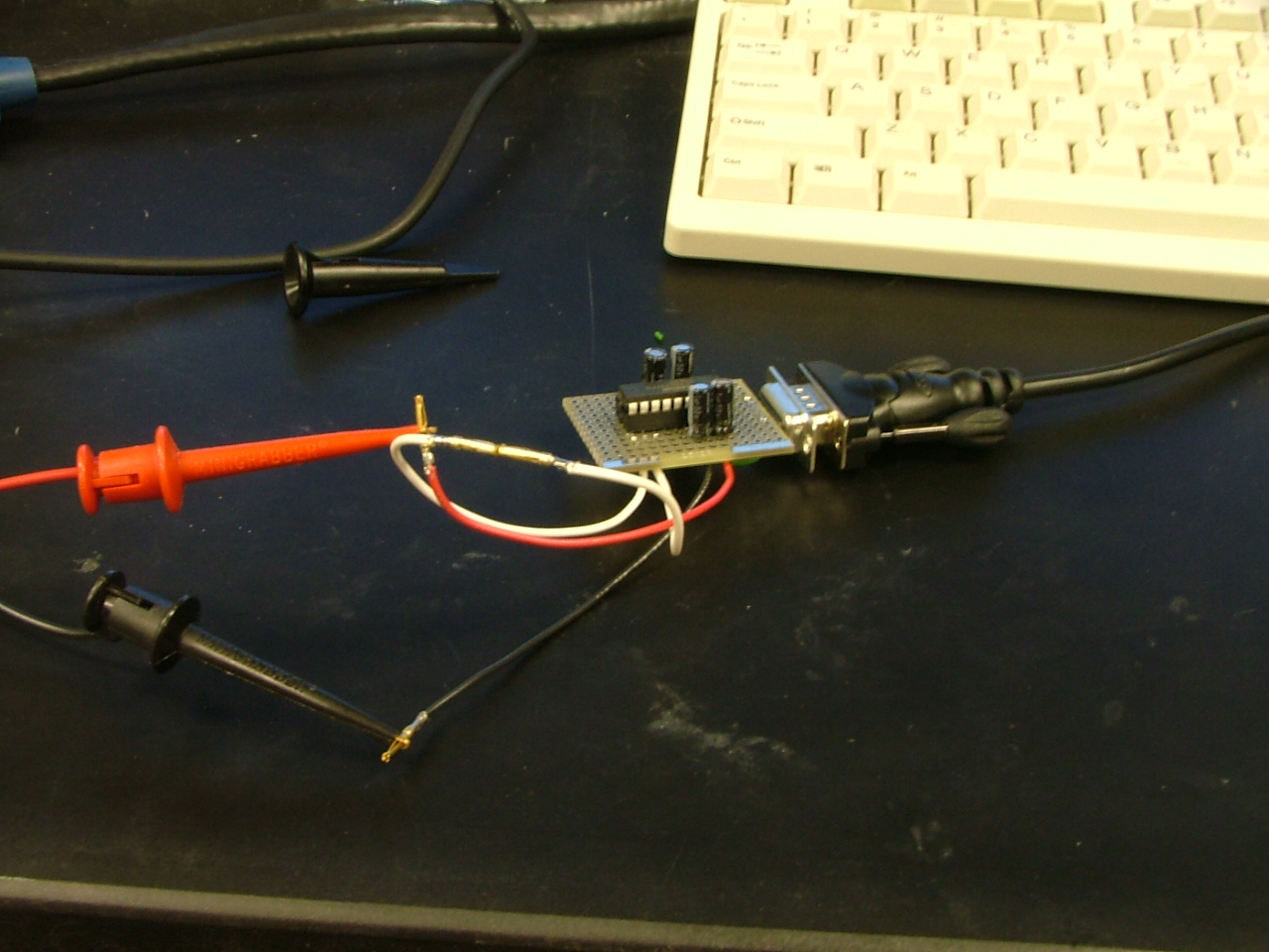
“I had a little bit of free time to work with the MAX3222 chips that Dallas Semi sent me. These have all of the features of the MAX232 (two TX and two RX channels) as well as shutdown and output enable. The best feature is that the chip can operate from 3.0V to 5.5V so it can be quite versatile in connecting both TTL and LVTTL devices via serial port. I ended up making a small board that has a female db9 connector and has the RX, TX and power leads for easy access.”
Thanks Nick.
Permalink
I dont get it, most of your posts are pretty cool. this is just a max232 on a protoboard, anyone who uses usart or rs232 know about them.
Permalink
Hey ph0rkeh,
Thanks for the feedback, I think it is nice to have projects with varying complexities.
It is a nice simple project, and with a free sample it could be done very cheap. Like most others one project leads to another. Have a look at what this project is being used for now!
http://microblog.routed.net/2007/02/18/how-to-get-root-access-on-the-linksys-wap54g-v2/
Permalink
“The best feature is that the chip can operate from 3.0V to 5.5V so it can be quite versatile in connecting both TTL and LVTTL devices via serial port.”
Everyone knows about the MAX232, but this board uses the MAX3222. Often times the designers make incremental improvements to their ICs that make them more versatile and here is one example. This board is to be powered off your embedded system and will run off any logic level from 3.0V to 5.5V.
Permalink
Why not use MAX@233’s? You only need one external cap for power smoothing.
Permalink
The MAX233 still requires a 5V supply. I wanted something that can support TTL, LVTTL and everything in between (both for supply voltage and logic).
Permalink
You probably don’t need to use electolytic caps. There are much smaller 1uF ceramic caps commonly available.
Permalink
the max233 doesn’t take any caps, I have a few of them but don’t use them. I use the max232a it needs only 0.1uf caps, the 104’s witch are everywhere. the reason I don’t use the max233 is because first of all its pretty big, 20 pins compared to the max232’s 16 thats fairly large, and to set it up is pretty annoying, some of the pins have to be jumped some grounded and blah blah. another upside to the max232 is there are alot of ‘wanna be’s that are drop compatible (and cheaper), witch is useful if you can only afford the cheaper ones, you can follow the same schematics.
I don’t know if there is one like this; but if I where to make a max232 like IC it would be 8 pins, VCC, GND, tx in/out, rx in/out, maybe a sleep or something and the other one not connected, and let it have internal caps, Id pay extra for the smaller size.
Permalink
All I meant by my first post was, it would have been nicer if you were to make your project more presentable before shareing with hackedgadgets witch is a real large fanbase, I didn’t mean to be rude or anything.
heres my rs232 level converter encloser project:
http://www.ph0rkeh.com/temp/rs232_level_box/
look at _main_fullwork.jpg first it explains it all
it contains a max232 for of course serial communication, wires from there to breadboard with headers (vcc,gnd,rx,tx), there are 3 leds (2 rx/tx, 1 bi-color status), and a AVR Attiny45 microcontroller for various status on the serial line and the max232, outputs the data to the bi-color led.
I also took a shot of the max232 and max233 next to each other in there, sorry for the crappy pics, crappy camera!
Permalink
Ph0rekh may be right, maybe I should have made the project a little prettier. The main point that I was trying to emphasize with post was that the MAX232 is somewhat obsolete and should be replaced by the MAX3222 or something like that in the hobby community. This goes along the lines of your first comment saying that anyone and everyone knows that you just put together a breadboard with a MAX232 and a few caps and you have a serial port transceiver. 5V logic levels are still dominant in the hobby and DIY community but almost every embedded consumer device runs at 3.3V logic (or sometimes lower!). It would be a waste of time to put together two different boards, so thats the novelty here. I will try to make posts that I forward to hackedgadgets a little prettier in the future.