
uC Hobby has a nice article about a project that uses an Arduino Microcontroller to read in temperature data and control an optically coupled motor using PWM.
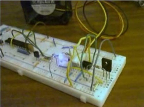
“Oscar Gonzalez gives us a simple tutorial for speed controlling a PC FAN and reading a LM35 temperature sensor with an Arduino microcontroller. He covers the use of an optocoupler, PWM (Pulse Width Modulation) and reading analog voltages with the Arduino. This devices is very simple. It consist of an phototransistor and a LED inside the same package. The phototransistor turns on or conducts current when the internal LED lights. The brighter the internal LED the more current can pass through the phototransistor. The LED and phototransistor are physically isolated from each other. This physical isolation protects the input side (the LED) from voltage spikes on the output side (phototransistor) and can provide the voltage translation needed for this project. When the LED is activated from the 5V Arduino the phototransistor will turn on and pass current for the 12VDC fan. The isolation provided by the optocoupler keeps the Arduino is safe from destruction.
The optocoupler’s internal transistor does not have sufficient current capacities to drive a DC motor (like our FAN) directly. To boost the current I used a BD137 transistor which can drive up to 1.5 Amperes. This power transistor is sufficient for controlling PC Fan motors. The PC Fan model I used runs needs about 300 mA.”
|
|
Permalink
Trippy, but the arrr-duino is more expensive to use like this.
Permalink
Meaby im missing something here, but why the optoisolation ,all supplys in the PC come to a single ground, id just use the trasistor
Permalink
GOOD MUSIC
Permalink
the music made me hot
Permalink
So maybe I’m missing something, but I don’t see an arduino there. What I do see is an atmega microcontroller, presumably running a custom bootloader.
Kind of rubs me the wrong way for some reason.
Permalink
Very nicely done!