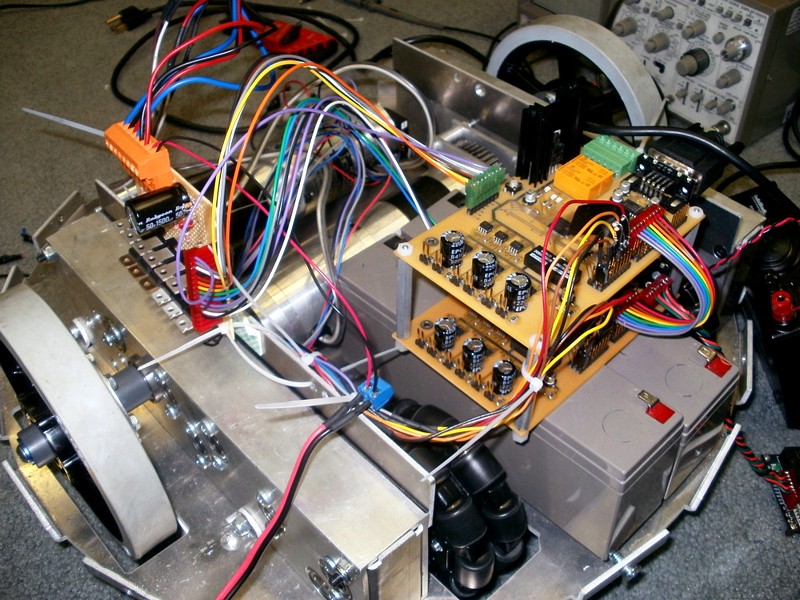
Andrew Angellotti has built and documented a DIY Brushless Motor Controller if you ever wanted to understand how a brushless motor controller worked or perhaps build your own this would be a great article to read. Once you have a good understanding of the heavy lifting electronics you should have a look at the second part of the DIY Brushless Motor Controller where Andrew goes over the code that makes the controller tick.
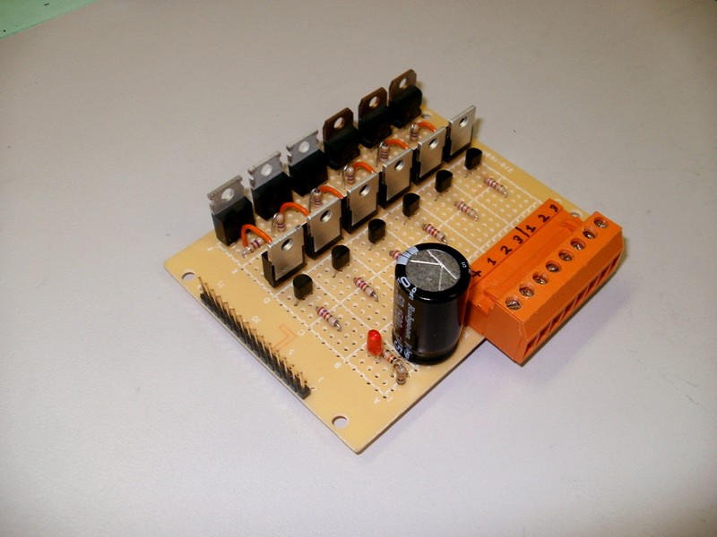
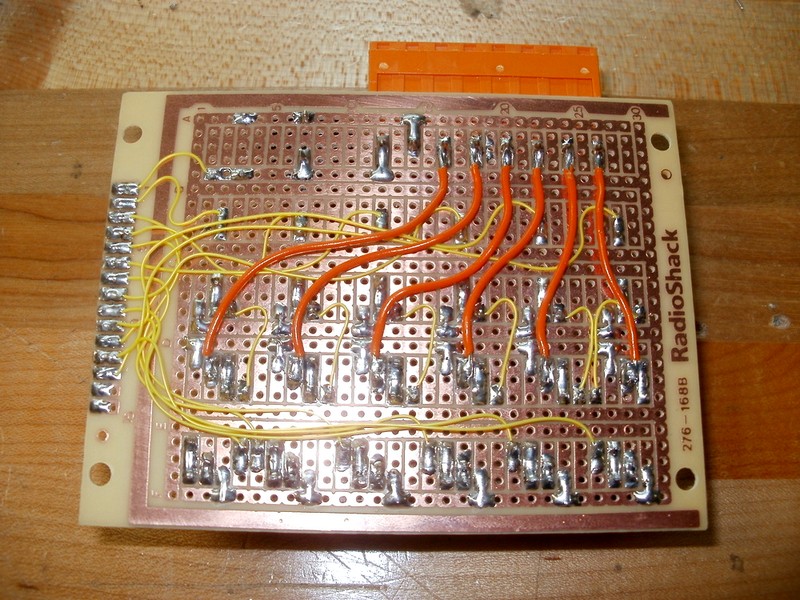
“The half bridges use TIP120 darlington NPN transistors on the low side (emitter goes to ground, collector goes to the output/high side), with a 470 ohm current limiting resistor between the base and the input to the board. Bring the corresponding input up to 5 volts or so, and the transistor turns on. Not much to that one. The high side is slightly more complicated. It uses TIP125 PNP transistors. The emitter of these is connected to the controller’s drive voltage, and the collector is again connected to the output/low side. To get these guys to turn on, we need to pull the base below the emitter voltage. This is done with a trusty 2N3904. The base of the TIP125 is connected to the collector of the 3904 through a current limiting resistor, and then the emitter of the 3904 is connected to ground. So when the 3904 is active, the base of the TIP125 is pulled low, and it turns “on.” Of course, don’t forget the 2k-ish current limiting resistor on the base of the 3904. This is then connected to the input to the board. So, looking purely at driving the inputs, 5V on a high-side input means the corresponding transistor turns on, just like the low side would if you applied 5V to a low-side input.”