
|
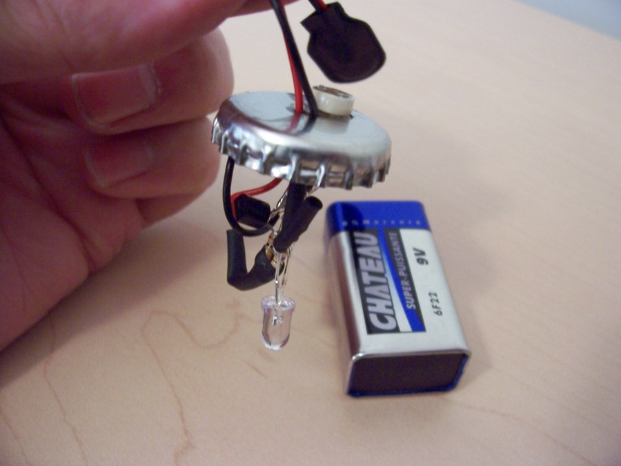
Blue Bawls Automatic Light Ok get your mind out of the gutter. I am talking about the beautiful blue glass bottle that the Bawls soft drink comes in. I tried one the other day and thought the glass bottle could be used for something interesting. At first I was just going to stick an LED into it, but I wanted something a bit more interesting. So I threw together a quick and dirty circuit that uses a photo-cell to turn on a transistor which powers an LED. The parts should cost only 2 or 3 dollars, and are available almost anywhere. (See page 2 for a parts list.) |
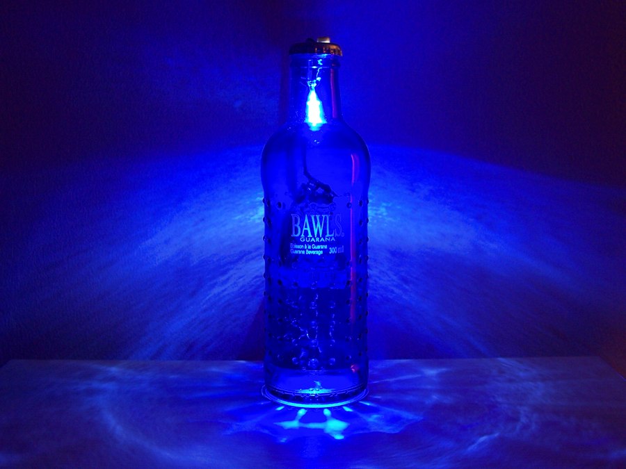 I am pleased with the final result, a single super bright white LED lights the glass very well and looks better than I thought it would. There is more than enough light to light up a night table or something similar in size. It is currently running from a 9 Volt battery since that was the simplest means I had, however a small plug in transformer would also do the trick. I am pleased with the final result, a single super bright white LED lights the glass very well and looks better than I thought it would. There is more than enough light to light up a night table or something similar in size. It is currently running from a 9 Volt battery since that was the simplest means I had, however a small plug in transformer would also do the trick. |
Video of the Blue Bawls Light in Action
Many people are asking who sings the song… The song is Weekend Full of Weekends and can be found here: Garage Band . Thanks to Andy McCaskey of Slashdot Review for turning me onto the site.
|
See how to make it on the next page. |
Permalink
This is cool 🙂 Cheap to build and and nice looking!
Permalink
Nice!!!! I want one… OK I guess I will have to build it 🙂
Permalink
Thumbs up dude!
Permalink
Say would you like to do my next music video
Permalink
Permalink
Permalink
Thanks for this! Now I know what to do will all those old bottles. God idea!
Permalink
Got here from hackaday.com . AWESOME hack! Awesome site from initial looks as well. Keep up the great work man.
Permalink
Bawls to the walls 🙂
Permalink
Permalink
awesome dude! way awesome. i’m buying 10 of each of those parts and lighting my whole house with these things. way to go 🙂
Permalink
You did this whole thing just so you could post a hack called blue bawls, didn’t you?
Well, the joke is on you, b/c the light is pretty cool. 😉
and you can turn these off!
Permalink
Thats the coolest nightlight i’ve ever seen
Permalink
Nice project! And to think I threw out tons of these bottles 🙁
Permalink
the hack is cool, but the video makes it awesome.
Permalink
Say goodbye to patio lanterns, I am going to string a bunch of these up. The blue light looks so nice and deep. I guess I will have so start by buying a case of blue bawls.
Permalink
Just a question.. how would you get this to work with 3 or 4.5 volts? it would be nice if i could shove the batteries in the actual bottle..
Permalink
This mod is really cool… But I NEED to what what song is playing in the video you made! 😉
Permalink
Seriously, nice. I’ll be making one of those. Though i’d really appreciate it if you could tell me what song that is, it’s damn good.
Permalink
The song is “Weekend Full of Weekends” and can be found here:
http://www.garageband.com/artist/vanderveen/songs
Thanks to Andy McCaskey of Slashdot Review for turning me onto the site:
http://slashdotreview.com
Permalink
Nice project. I don’t have any Bawls laying around but I am thinking about making one from a green plastic bottle. Thanks for a great project! By the way the song ROCKS. I am downloading it right now 🙂 I think it will be a permanent fixture on my IPod!!!
Permalink
how cool. and how simple =)
Permalink
i sure like that song playing in the background
Permalink
Nice 🙂
Here is another use:
http://haphazardhacks.blogspot.com/2005/07/lan-parties-can-get-mighty-hot-what.html
Permalink
Alright, thanks Alan, and by the way, your a freaking genius for thinking this up. I’m going to have one of these made by The time the weekend hits. 😛
Permalink
Love it, Love it, Love it! The tune is great never heard of them before. Consider Hacked Gadgets bookmarked. You have some real interesting stuff here, thanks for your hard work.
Permalink
The drink is outstanding and now I can justify paying a bit more for it, no one else has a funky glass bottle like this one!
Permalink
i havn’t the slightest knolage in the
circuit stuff could somone clue me in as to how to make it
thanks. please
Permalink
sorry did not know there weere pages
Permalink
Thanks for the great comments guys (and gals)!
Hey Only Me(#28) there is a schematic on page 2.
Permalink
Hi Arthur (#17) you could do it with 4.5 Volts (3 AA batteries) You would need to change the two resistor values though. The 470 ohm resistor could be replaced with a 33 or a 44 ohm resistor. The 100K ohm resistor would take a bit of experimenting to find the optimal value though.
Permalink
Permalink
Hey guys, I wanna do this but I want it plugged in to the wall, and also I want a button with 3 settings, AUTO, OFF and ON. How would I come about that. so that in auto, it will turn the lamp on at night and you know the on would override the sensor and so on. how would I do this? email me at elmetal@bellsouth.net please this is a genius idea having the bawls as a lamp. any help would be appreciaed… thanks guys!
Permalink
Hi Felipe (#33),
What you would need is a single pole, double throw (center off) switch.
The center will be off. On the switch connect the 9 Volt positive wire to the common terminal (center).
Then to do the auto and on mode you will need a resistor. Connect one end of the 1K resistor to the transistor base and the other side of the 1K resistor to one of the empty switch terminals. Then connect the last empty switch terminal to where 9 Volts was connected in the original circuit (top of 100K and 470K resistors).
As far as powering it from the wall look for a wall plug that is rated at 9 Volts DC, with a current at least 50mA (not sure you could find one smaller but just in case). This would allow you to use the same values in the schematic. However you could use other power supplies with different voltages by adjusting the resistor values.
Here is more information about this in the forum (including a schematic):
http://forum.hackedgadgets.com/viewtopic.php?p=157
Permalink
Kick ass idea. Felipe has a good enhancement though, I think making a hole near the bottom of the bottle and have a cord running up the inside of the bottle to the electronics and LED at the top would work great. Not sure where the switch would go. I guess there might be room for it on the cap beside the photocell if they are positioned well. Thanks for providing the new schematic for the switch, it rocks!
Permalink
hmm I really want to make this! buy I’m not informed about circuitry or using schematics 🙁 perhaps you can post something for us who don’t know anything about it? or a step by step on what goes where >
Permalink
When I did this, the photocell only gets brighter with more light. And when there is no light, there is no light. Does anyone know why?
Permalink
Permalink
“When I did this, the photocell only gets brighter with more light. And when there is no light, there is no light. Does anyone know why?”
YOU DUMB BASTARD
YOU WRIED IT BACKWARDS
CHRIST!!
Permalink
Hi Aaron (#37),
What you have to do is switch 2 wires around. Keep the photocell and 100K resistor connected together at the common central point (the way they are now), and swap where their other leads go. This will allow it to work in reverse to what it is doing for you now.
Permalink
ALSO WHAT ABOUT THE CAP ISN’T THAT CONDUCTIVE
Permalink
Hi Jiggy (#41),
Yes the cap is conductive, center the leads of the photocell in the holes when gluing it in place. It is actually fine if one of the leads shorts out to the cap, but try to keep them both centered.
Permalink
$2-3 dollars? Are you joking? The parts list provided totals $8.39 alone…. and that is NOT including a 9v battery. Another 3. $11.39 plus the bottle of bawls.
Thanks buddy, way to make things realisitic and honest.
Permalink
Hey #43,
I don’t think I am misleading anyone!
NPN transistor: $0.69
PhotoCell: $0.56
LED: $0.50
Resistors: $0.4
Battery Snap: $0.45
Total: $2.60
Many of the parts come in 5 packs etc. I didn’t include the parts that are NOT included in the project in my price estimate. If you shop at a place other than Radio Shack you could do it a bit cheaper, but Radio Shacks are everywhere and convenient for most people.
Permalink
The out of pocket cost to build this project is NOT $2-3. You CANNOT purchase each of those items individually. The parts list that you personally provided, when placed in a shopping cart and purchased is $8.39+shipping. In the real world “spare parts” are factored in to the total cost of a project.
Also, hey #44 “Total: $2.60” , Oh, so a 9v battery costs .40 cents eh? Where do you shop?
Maybe you should indicate as such in the build list. This all is absolutely misleading.
Permalink
Well to each their own, I am sorry that you seem to have such a strong opinion on the way I calculate project costs. For example if I am building a project that needs 10 resistors and I purchase a pack of 100. I still have 90 in my parts bin so I personally don’t factor the unused parts into the build price. If I did that then this project might have cost me $50 since I have lots of spare parts 🙂 Batteries are not usually included in project costs since batteries will be an ongoing expense. Plus if you are so worried about the price go to a dollar store and get the 2 pack of 9 Volt batteries for a buck. I am also not considering the cost of the bottle in this, if you don’t have a pop bottle kicking around you will have to shell out some more money for some pop. If you want to think of the project as a build 5 for $15 dollars maybe that is the way to think about it 🙂
Permalink
oh my god,
is appearing very beatifull 🙂
Permalink
Hey Ozgur (47), thanks! You have one cool web background image on your site!
Permalink
Question: Why did you use such a high resistor value for your LED?
I must be missing something…
If your running a white LED at 3.4v, 20ma, you should use ~300ohm resistor connected to the 9v+ terminal.
Your using a 470ohm resistor???
Permalink
Hi Ryan(49),
Nope you didn’t miss a thing 🙂 This is to allow the unit to last longer (since it is battery powered). These LEDs actually run have a MAX current of 30mA so you could even go with something like 220 ohms.
http://alan-parekh.vstore.ca/product_info.php/cPath/4_6/products_id/14
I also wanted to be conservative with the resistor value since people might build it with other LEDs that have different voltage drops.
Permalink
I don’t understand the diagram but I want to make one. Can you take pictures of the steps needed to connect the electronics?
Permalink
This is an excellent project however i cannot get mine to work. the light is constantly on. i tried reversing leads and i double checked everything. can you help me?
Permalink
Nevermind it turns out that my photo diode was faulty i swapped out each part one at a time and it worked when i put a new one in.
Permalink
HI Steve (52,53)
I hate that, the worst is when you have two bad devices… Glad you got it going though 🙂
Permalink
Hi Len (51),
I don’t have detailed pictures of the construction other than what I have posted already. If there are some other people who would like it done I will post it soon. If not give me a while and I will get around to it. I am happy that you want to give it a try as your first step in electronics though, that is the main purpose of this site and http://www.alan-parekh.com .
If you need help in identifying the components have a look at this project over at Instructables you can hover over the components and it will tell you what they are.
http://www.instructables.com/ex/i/745AE9A61B6610299AD7001143E7E506/?ALLSTEPS
Permalink
quit complaining about the price you cheap ass. if its to much money don’t build. simple as that!!!
Permalink
Hi, I have a question with the blue bawls light. I dont know where to start. After I drill the 3 holes in the cap for the photo cell. Whats next I cant figure it out from the pictures or the instructions. Help me please
Permalink
Alan this is a awsome build. I just got a bottle of Bawls never had it before or even seen it. I found the bottle from there web site I had to drive a couple miles for it but it was worth it. I drank it up it was the best energy drink I had and tasted good. I ordered some parts from you. Cant wait till I get them too start building. I see you have a resistor chart on your site too find out what size you need the only thing I want too know is when you have a transistor how do you know what you need for resistors? They only show one resistor being used in the diagram I want to know how you figured what you needed for resistors for future builds. Thanx
Permalink
Hi Maxx (57),
There are many ways to build it as long as it is electrically the same as the schematic. I have built another one taking many pictures along the way and posted it on the Instructables, have a look. If you have any other questions please ask 🙂
http://www.instructables.com/ex/i/745AE9A61B6610299AD7001143E7E506/
Permalink
Hey Don (58),
Yeah Bawls is great! The transistor is simply acting as a switch in this case. The collector (C) emitter (E) voltage drop is negligible so you can just ignore it for basic calculations. You will notice that the current is lower than the MAX for these LEDs. This is because the unit is running from batteries and the way it is set gives the best light output/run time balance.
Alan
Permalink
Great Project;
This is exactly what I am looking for, but for a different purpose. I work a local Ren Faire, and I end up getting to my car after dark, in about a 60 acre unlit parking lot. My car is dark, the lot is dark, and the background is dark… I want to have a battery powered device in a window or two that blinks and helps me find the car. The photocell will help it not run during the day!
Thanks!!!
Matt
Permalink
Hi Matthew(61),
That sounds like a fantastic application! You could have this sitting on the front dash of the car and plug it into the cigarette lighter instead of using a 9 Volt battery.
Permalink
Alan,
Great little project. I just finished tossing it together with a litre bottle of Harvey’s Bristol Creme (a little bigger, but darker blue). Thanks!
And also – kudos for ignoring the idiot remarks on price, etc.. The world is full of idiots, but the internet seems to focus them… 🙂
Cheers,
Ed T.
Permalink
Hi Ed 63,
Glad you had fun putting one together. I would love to see it, if you want why not post a picture in the forum:
http://forum.hackedgadgets.com/viewforum.php?f=2
We also have a new place to store images for use in the forum also, feel free to take advantage of it also:
http://forum.hackedgadgets.com/image_gallery
I know what you mean about the guy harping on about the price. I guess someone has to over analyze everything. I am surprised he didn’t factor gas money into his calculation since it isn’t free to get to the store and back. 🙂
Permalink
Hey Alan,
Awsome Hack!
I’m having two problems, One is that I cannot read the resistors (the colours) so I cannot figure out what resistor I have to use and I cannot figure out the transistor either because mine is labelled diferently. Mine’s labelled ABC while yours is labelled BCE? Could you help me?
Thanks
Permalink
Hi Nate,
On page 2 there are links for the two resistors and the transistor. Click on these and look at the picture of them. The picture is the actual resistor color code and transistor pin out. Transistors all have three pins a base (B), collector (C) and emitter (E). Most small transistors have the same in out, or post the model of transistor and I will look it up for you.
Permalink
hey! awesome hack
i have wired mine up and have the same problem as 37
i was wondering if anyone could help me
Permalink
Hi, I have a Question. When you start to solder the NPN Transistor , I put to much heat to it. And When I fix the whole light fixture. the light comes on, but it comes on very dull. Could it be that the Tranisitor is burnt out? Please Help me.
Permalink
Dude this hack is awesome!!! How could you get this to run off of a USB cable instead of a 9v battery???
Permalink
Hi Mark (69),
Hacked Gadget forum member Modio has done exactly that. His creation can be seen here:
http://forum.hackedgadgets.com/viewtopic.php?t=122&start=0&postdays=0&postorder=asc&highlight=blue+usb
Join the forum and ask Modio some questions if you need 🙂 everyone in the forum is very helpful.
Permalink
Hi Maxx (68),
Transistors usually fail completely when they go. You might have to change the 100K resistor to match your particular photo cell.
Permalink
Hi Tyler (67),
Does your photocell increase in resistance in the dark? A standard photocell does. Here is some more information about their basic operation, test yours and see if it is operating correctly.
http://en.wikipedia.org/wiki/Photoresistor
Permalink
Cool dude, that looks wicked sick. Nice idea i give you props
Permalink
These look great and make great garden lights for parties etc.
except that over in the UK we have no bawls so Sherry bottles will have to do!!
PS
Do you know where can I down load the .mp3 for my pod??
Permalink
this looks really cool. ive got all the parts to make it but the schematic thats frirst posted is a little over my head. can anyone post a more step by step schematic?
Permalink
nevermind i found a diagram that was like the one i asked. but yea i cant wait to build it
Permalink
Hi Alan,
Today, I went out to buy some parts to try and make this, but when I tried testing it, the light does not turn off no matter what, and it is VERY dim. Any ideas why? Here are some pictures of it assembled: http://robm.drunkencoders.com/led_project/
What did I do wrong? 🙁
Permalink
i looks like your transistor is backwords just flip it over and put the one you have to the led to the photocell
Permalink
Nope, did not work, same issue. 🙁
But thanks for the fast reply. 😀
Permalink
Fixed it. 🙂
Permalink
how did you fix it? i had the same problem i hooked it up and nothing worked
Permalink
Diagram (With labels): http://robm.drunkencoders.com/led_project/finished/IMG_0684.png
Diagram (With labels & everything color coded): http://robm.drunkencoders.com/led_project/finished/IMG_0684_painted.png
Hope this could help. 😉
Permalink
I cant get hold off the 2n 4401 trasisator is there any others i can use i am in the uk thanks.
Permalink
I’m trying to build the same thing and have run into a bit of a snag, but the light on mine doesn’t come on. I’ve verified that the battery, photo-cell and LED are good; not sure how to check a transistor, but I have tried two and they are brand new. Both are 2N4401s, just like yours. I have tried varying the resistors, but I am afraid to go too low because I don’t want to burn out any of my components.
Pictures of the non-functional circuit are here: http://www.flickr.com/photos/71184440@N00/tags/nonfunctionallampcircuit/
Permalink
Hi Wizz,
The 2N4401 is a common transistor with many others that are compatible. See if you can get a 2N2222 or a 2N3904 these would also work well.
Permalink
Hi Eris,
From what I see the circuit looks correct. Keep everything the way it is and pull out the photo cell. If the light turns on you will need a different photo cell. The one required for this circuit is the most common type that goes towards an open (high resistance) when in darkness.
Permalink
Thanks, but as it turns out, it was the last thing that I could have expected. It was the copper wire. I didn’t realise it, but that’s wire for winding electric motor coils, so it’s coated with a transparent insulator.
Well, it works now and looks nice. I have a blue vodka bottle filled with glass beads and an 1100mcd white LED, so it’s a soft light, good for a night light I think.
I’ll post pictures tomorrow.
Permalink
LOL don’t you hate it when something that is not even considered is the problem… Darn those non conducting chunks of copper 🙂
Glad to hear you got it going. I look forward to see your pictures.
Permalink
hey Alan…i must say it looks fantastic! but i was wondering, can the same concept be used to power any circuit? I mean using the photocell but ofcourse replacing the led part with the +V of a different circuit (maybe an led flashing sequence or something)?
Permalink
Sorry for the long delay, but here are a few pictures of my lamp: http://flickr.com/photos/71184440@N00/tags/vodkalamp/
I’m afraid there are only three for now, but I might take more this evening. They’ll be under the same tags.
Permalink
hey guys,
I just built this circuit because its friggin awesome and I completed it and it WORKS! however, the “super bright” led is REALLY REALLY faint. I was wondering how the hell I can make it brighter? I tried changing the resistors to around 200ohms instead of 470, but that didnt do much, any ideas? (I also changed batteries, to no avail)
Permalink
ok i am stuck mine looks just like your in the pics but i have a 2n2222 transistor but even without the photo cell the light still stays on help me please.
Permalink
Hi Graham (91),
When it is on (as bright as it can go) meter the voltage from the transistor C to E. There should only be a small voltage there, if there is a large voltage there you might have to adjust the 100K ohm resistor to bias the transistor more.
Alan
Permalink
Hi Wizz (92),
Actually the light should turn on as the photo cell gets dark, as the photo cell gets dark the resistance should increase. Therefore by removing it from the circuit it should turn on as bright as it can. Meter the photo cell and see if the resistance changes when it is exposed to light and dark. It is the low resistance when in the light that turns off the transistor.
Alan
Permalink
Hi Alan
Fascinating! I do not know the bottle or the product but here in
Bristol UK – famous for hundreds of years for its ‘Bristol Blue’
Glass – I think I shall have to give it a go. I particularly like
the development of the idea of the batts’ being inside the bottle
through to an OS power source. I can just see them gracing the OS
table during the warm summer evening. (Not a grammatical mistake;
summer here was July 29th last year, at about two o’clock). BUT,
why not make a plain plinth for the bottle to stand on? The plinth
could hold all the gubbins with a simple jack plug connector
transferring power to the LED through the female part glued into
a hole drilled in the base of the bottle. Suspend the LED between
two rigid wires stretching half way up the bottle. Ok I haven’t
considered the photoelectric cell, it’s midnight, the creative
juices have dried up and I need my kip!
Thanks for a wonderful site
Whizz (with an ‘h’ not the other fellow)
Permalink
Hey folks…I’ve designed a pcb for the Bawls light (original version) that holds the 470 ohm
resistor, a 100k trimmer (replaces the 100k resistor for variable sensitivity) and the 4N4401
transistor…it has external holes for a 9v supply, the photocell, and 2 leds (you can use one
led by just jumpering the 2nd terminal to complete the trace). The upshot of all this is that
the board itself is only .5″ x 1″ (1 sq. inch) and fits perfectly inside the bottle. Let me
know if you want the file, and I’ll send (e-mail) it to you. It’s an Express PCB file (*.pcb);
just for the record.
Permalink
I have taken and covered most of the LED with heat shrink tubing to hide part of the light source. In some cases it looks better. I’ve been using this circuit to make lights for my young relatives and their friends. I have a huge one gallon Seagrams 7 Crown bottle this circuit works great for. Way back when I was a youngin I used to light it with a single 7 watt incandecent bulb. Now all my young nephews want my Seagrams bottle.
Permalink
Hi FredEx (97),
Sounds like a great way to make the project.
Step 1: Build the LED circuit
Step 2: Drink a bottle of Seagrams to put it in…
Permalink
Can sum one email me a scematic for the bawls led light not the one with the switch just the one shown email me at like2bme15@yahoo.com
Permalink
Hey Me (99),
It is on page 2.
Permalink
when i did this i think i messed up but i cant find when i have taken and put it back together many times and still when it is in the light it turns on and when its in the dark it turns off if you know what i did wrong please email me at like2bme15@yahoo.com
Permalink
Hey, I’m assuming this will work with a 2N3904, is that correct? Or does it have to be a 4401 for some reason I don’t quite comprehend?
Permalink
Hi Mr. Cakes,
Yes a 3904 will work just fine.
Permalink
Another suggestion:
use coated coil wire to power the device, the wire is very fine (think fishing line) and it also provides alot of resistance. With about 2 feet of it, i didn’t need a resistor on the led, although i am going to run another foot to be on the safe side.
Note: you can buy small rolls of coil wire from radio shack, or you can sometimes get some off of a transformer)
Permalink
Alan, I have tried to build this with the switch to no avail. Either nothing works and the battery gets hot,
or the switch has basically no effect. I have drawn a diagram of my build, kind of a 3d schematic.
It is on pdf format. Can I email it to you so you can see if I am just WRONG? or making a simple error?
Permalink
Hi Phil,
Have a look at this post http://forum.hackedgadgets.com/viewtopic.php?t=114 , there is a schematic for how to wire it. You can email your PDF to admin at hackedgadgets.com
Permalink
Permalink
My boyfriend made bottles with this kind of light for my students last spring.
Permalink
ok, i made one…theres one problem. the led i bought from radio shack blows, such a dim light. are there any
electronic stores i can purchase a bright led from besides radio shack? this light just isnt cutting it and i really dont
want to go through the trouble of ordering it off the internet.
Permalink
ok im positive its not the light anymore. My LED can go brighter…but only when the LED/NPNTransitor touch….but twhen they touch the photocell
stops working. how do i make my LED emit more light?
Permalink
Permalink
Awesome, man
Permalink
does anyone have AN E-MAIL ADDRESS OF AN AUTOMATIC NIGHT LIGHT COMPANY.IF SO PLZ SEND ME AN EMAIL WITH THE DETAILS THANK YOU MANCHESTER_UNITED_RULE_@HOTMAIL.CO.UK
Permalink
this is really cool, this thread looks dead though.
but i need HELP!, im not very good with circuits, and i am having an extremely difficuld time calculating voltage drops and differences in currents and volts, im using a different LED, but i dont know what you are using to compare it to.
would it be possible to stick like 10 or more of these LEDs to the project? if so would it require a series or parallel circuit? i have no clue.
Permalink
is it possible to replace the photocell with a IR reciver so that it could be controlled via external device, and of not what about powered on/off by a switch?
Permalink
Hi Michael (115),
Have a look here http://forum.hackedgadgets.com/viewtopic.php?t=114
Permalink
no
Permalink
Wow, that’s really bad ass.
Permalink
Thats freaking awesome, in College I had lots of bottles of this stuff in my room filled with black light responsive liquids.
Permalink
I just finished my project about LED lighting for holiday use. It is custom made and I did all the design by myself. I got some idea from this website http://www.lunaraccents.com and study from some other sources online.
Permalink
sorry to bump this thread
but i built this light to the exact specifications, i have made 4 of them but none of them work they way they should.
the photocell dims the light in darkness and brightens it when light is introduced.
i’ve wired it every possible way i can and it still wont work.
im thinking i bought a bad batch of photocells…
and i’ve gone through a few transistors to make sure they weren’t ruined by the constant re-wiring.
any ideas?
Permalink
you should stick it near a door at night so it looks like something wierd is going on
Permalink
i DRINK ALOT OF bAWLS. NoW i KNOW wHAT To do WItH aLL of thE bOTtLES. iF oNLY i WaS AN eLeCTRriCIAN.
Permalink
Awsome!! That is sooo COOOOOOOOOOOL! Congrads on the idea.
Permalink
see, what you really need to do is instead of lighting candles for sex, line the room with these mothers.
Permalink
Hey, I wanted to make one of these with the switch, like someone asked earlier (posts 33 & 34). However, the link posted in #34 is dead now. Can anyone help me out with a schematic for this variation of the project?
Permalink
Hi sshah87,
Please check back later, the Hacked Gadgets forum will be back shortly.
Permalink
Ok, I’ll keep checking back. Thanks for the quick reply.
Permalink
I have it set up exactly the same way as in the pictures and it makes the LED turn off when the lights go on and stay on when there is light…
I read that your suppose to switch the leads.. I’ve done so but then it stays off and does nothing.. Help please
Permalink
what if i would like to use incandecent bulb instead of LED?do i need to change the size of the resistors and transistor?
Permalink
Hello
I was wondering, will it work to combine this project with http://www.makezine.com/blog/archive/2007/11/make_a_joule_thief_weeken_1.html to save battery? if it is possible, how will the schematic looks like? will it be like this: http://www.e.kth.se/~sheng/light.jpg?
I am not so good at electronics hehe 😛
I was thinking like using a AA/AAA battery that can be fit inside the bottles, any idea how long it will last? and will the LED be bright enough with this method?
Permalink
Hi Xander,
It would be difficult to do with an incandescent since they draw so much power.
Permalink
Hi Avin,
Your idea would probably work, I think your best bet to make the circuit work would be to simply feed the existing negative and positive of the circuit from the higher voltage made using the joule thief.
Permalink
Hi Alan
I am not so sure that I understand what you mean? (^_^)’
Permalink
Just replace the existing places where the negative and positive connect.
Permalink
Has anyone made a bottle lamp using a plastic bottle? I got a very special collector’s bottle while I was overseas, and want to preserve it as a small night light or lamp. This glass bawls lamp (I love the bawls soft drink by the way) looks fantastic, but I’m worried that if I tried this with small plastic bottle, it might melt. Any suggestions? I’ve scoured the net and found nothing helpful. Thanks in advance!
Permalink
Permalink
Hello Alan,thanx 4 the project,and 4 all the answers you gave-read them all
i came via hackaday,but i’m looking 4 a similar circuit in which a microphone is the ”switch”
as i’m not that good at …tronics
what i mean is that when a mike pics a sound it triggers the transistorwhich switches
on the led…
might need an opamp to amplify the signal?
if you could help me with the schematics,i’d …
thanx,benz
Permalink
Yo dudes
I love your funky ideas on lights
they are rather rivetting and enjoyable to the eye
keep reaching for the stars!
xx
Permalink
Hey Alan,
Cool Bawls hack! I used to drink sooo much of those things when I worked at Office Depot’s corporate office that I had a cubicle built out of them(figuratively)…but hey, there was another hack that you did which was the ‘create your own embroidery machine”, but hacked gadgets took it down I think, because it’s no longer there. Do you still have it, and if so, could you repost it or email it to me? That would be awesome if you could! Thanks, and keep the hacks coming!!
Permalink
Hi Kruz,
Sounds like a cool cube. 🙂 The article is here http://hackedgadgets.com/2006/04/07/diy-computerized-embroidery/ but it looks like the site that was linked to is gone…
Permalink
Permalink
Hey, i have a 12V battery and 12V led panel. I was wondering if someone knows what transitor and what riesitors i would need to use for this setup? Im trying to set up my greenhouse so the light automatically comes on during night. Any help?
Permalink
hi i m prajesh in electrical engineering sudent. please give me a parts and their photos
of smart continuity tester> your faith fully,
prajesh.
Permalink
I’m trying to do this project, but the 9v battery won’t fit into the top of the bottle. I looked at your pictures, and my bottle is different than yours. It says 296 ml and 10 fl. oz. I can’t find any bottles like the ones in your pictures. Do you know of anywhere to get those style bottles from?
Permalink
Hi Matt,
The battery is actually outside the bottle. It is hanging in the back.
Permalink
Permalink
Hi alan
Nice hack :). It gets a high rating in the fun-factor for $$$ category :).
I’m planning to use this in various applications so I have some questions.
1. Is the 100Kohm resistor the max value needed for any voltage and LDR, i.e. can a buy a variable 100K pot to allow adjustment for different voltages and LDRs?
Or should I buy a 200K pot if I want to use it with 3v and 12v for example? Plan to use the pot to pinpoint the fixed value needed.
I have this LDR http://dk.farnell.com/eg-g-vactec/vt90n2/ldr-series-vt900/dp/1652637 and this http://dk.farnell.com/eg-g-vactec/vt935g/ldr-series-vt901/dp/1652638
2. I presume that you just get the resistor value for the LED by the normal (Vin-Vused in LED)/A used by LED?
3. Is the middle leg always B and then you can just swap outer legs if it brightens instead of dims when light?
Permalink
Hi Steffen,
There are lots of different LDR devices, I think the ones that I used go to about 1M ohm when in complete darkness. If you got a 1M pot you could find the sweet spot for your needs. The base is usually the center pin but this is not always the case. If you flip the 100K resistor and LRD around that will change the way it reacts to light.
Permalink
hi….
nice project ….can any one send me its details like circuit diagram and components required…
thanks in advance,,,,,
Permalink
Hi Steve,
All of those details are provided (there are multiple pages, look in the lower right corner of the article)
Permalink
Permalink
Hey guys,
I bought the required components but, I have just one question… what size Photocell do I use? Thanks for any helpful comments.
Permalink
Hi Contraman,
The size doesn’t matter, just make sure that it increases in resistance when it gets dark.